HP ENVY 15-u010dx HP ENVY x360 Convertible PC Maintenance and Service Guide - Page 65
Pull the hinge covers off the hinges, that secure the hinge covers to the hinges.
 |
View all HP ENVY 15-u010dx manuals
Add to My Manuals
Save this manual to your list of manuals |
Page 65 highlights
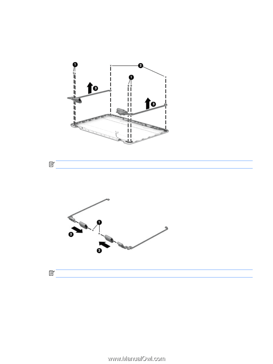
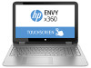
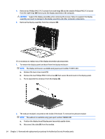
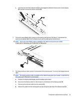
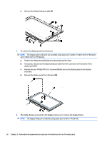
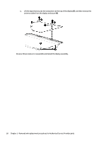
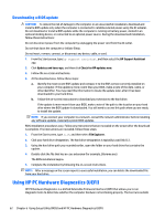
a. Position the display enclosure so you can access the internal parts. b. Remove the four Phillips PM2.5×4.0 screws from the bottom of the hinges(1) and the two Phillips PM2.0×3.0 screws (2) from the top of the hinges that secure the hinges to the display enclosure. c. Remove the hinges from the display (3). 7. The hinge covers are installed on the display hinges. To remove the display hinge covers: NOTE: The display hinge covers are available using spare part number 774597-001. a. From the inside of the hinge covers, remove the two Phillips PM2.0×3.0 screws (one per hinge) (1) that secure the hinge covers to the hinges. b. Pull the hinge covers off the hinges (2). 8. The antenna cables are installed in the display enclosure. To remove the antenna cables: NOTE: The antenna cables are available using spare part number 774590-001. a. Lift the tape that secures the antenna cables to the bottom of the display enclosure (1). b. Remove the cables from the clips built into the enclosure (2). Component replacement procedures 57
-
 1
1 -
2
-
3
-
4
-
5
-
6
-
7
-
8
-
9
-
10
-
11
-
12
-
13
-
14
-
15
-
16
-
17
-
18
-
19
-
20
-
21
-
22
-
23
-
24
-
25
-
26
-
27
-
28
-
29
-
30
-
31
-
32
-
33
-
34
-
35
-
36
-
37
-
38
-
39
-
40
-
41
-
42
-
43
-
44
-
45
-
46
-
47
-
48
-
49
-
50
-
51
-
52
-
53
-
54
-
55
-
56
-
57
-
58
-
59
-
 60
60 -
 61
61 -
 62
62 -
 63
63 -
 64
64 -
 65
65 -
 66
66 -
 67
67 -
 68
68 -
 69
69 -
 70
70 -
71
-
72
-
73
-
74
-
75
-
76
-
77
-
78
-
79
-
80
-
81
-
82
-
83
 |
 |