HP ENVY 15-u010dx HP ENVY x360 Convertible PC Maintenance and Service Guide - Page 62
CAUTION, The webcam module is mounted on the inside of the bezel. To remove the webcam module
 |
View all HP ENVY 15-u010dx manuals
Add to My Manuals
Save this manual to your list of manuals |
Page 62 highlights
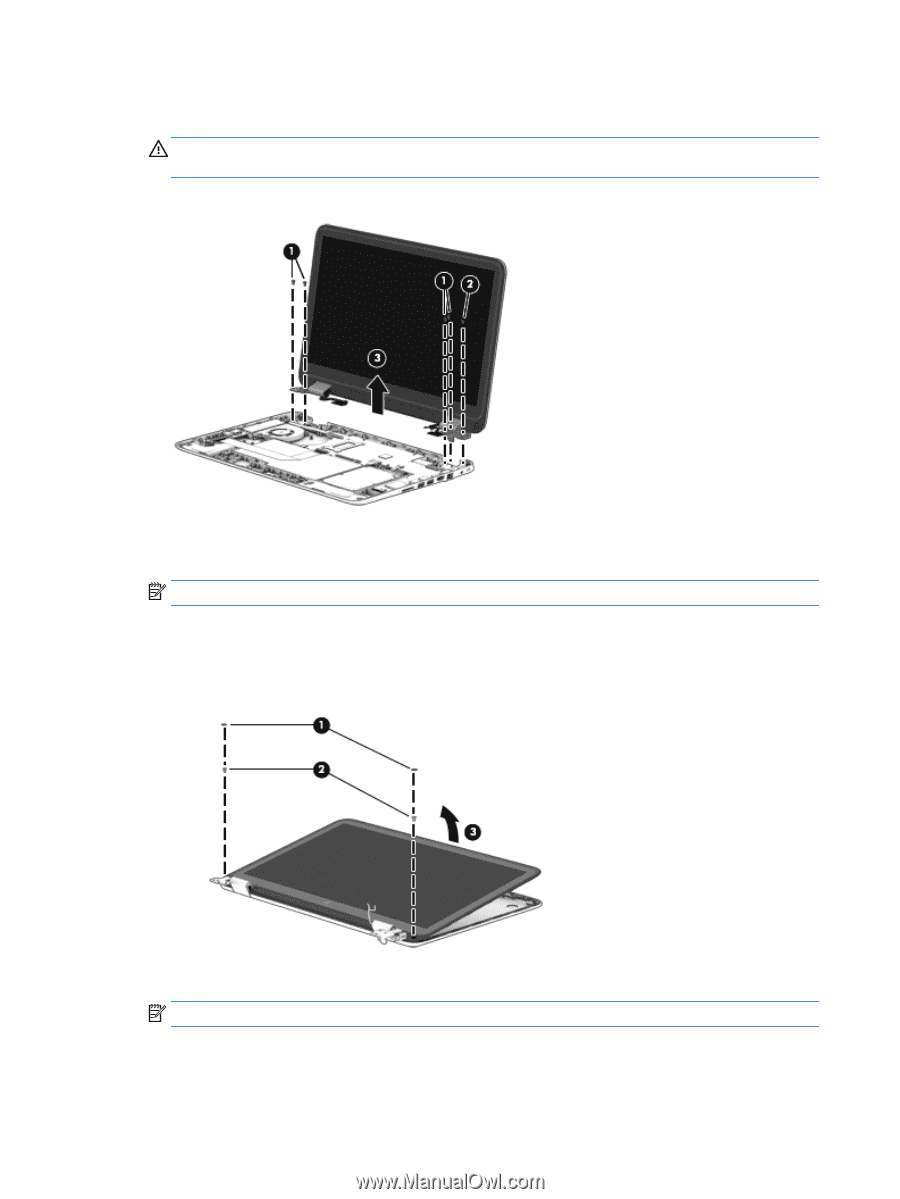
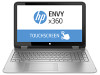
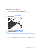
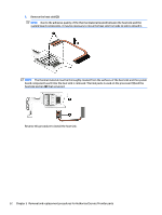
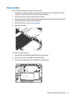
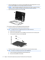
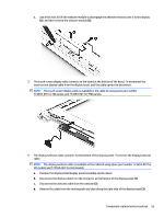
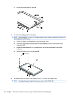
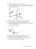
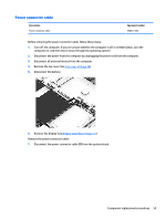
4. Remove two Phillips PM2.5×5.5 screws from each hinge (1) and the smaller Phillips PM2.5×3.6 screw from the right hinge (2) that secures the display assembly to the computer. CAUTION: Support the display assembly when removing the screws. Failure to support the display assembly can result in damage to the display assembly and other computer components. 5. Remove the display assembly from the computer (3). If it is necessary to replace any of the display assembly subcomponents: 1. To remove the display panel and bezel from the display enclosure: NOTE: The display enclosure is available using spare part number 774591-001. a. Remove the two screw covers (1). b. Remove the two Phillips PM2.5×4.0 screws (2) that secure the enclosure to the display panel. c. Pry to separate the enclosure from the display (3). 2. The webcam module is mounted on the inside of the bezel. To remove the webcam module: NOTE: The webcam is available using spare part number 768040-001. a. Position the display bezel/display panel assembly upside-down. b. Disconnect the cable (1) from the module. 54 Chapter 5 Removal and replacement procedures for Authorized Service Provider parts
-
 1
1 -
2
-
3
-
4
-
5
-
6
-
7
-
8
-
9
-
10
-
11
-
12
-
13
-
14
-
15
-
16
-
17
-
18
-
19
-
20
-
21
-
22
-
23
-
24
-
25
-
26
-
27
-
28
-
29
-
30
-
31
-
32
-
33
-
34
-
35
-
36
-
37
-
38
-
39
-
40
-
41
-
42
-
43
-
44
-
45
-
46
-
47
-
48
-
49
-
50
-
51
-
52
-
53
-
54
-
55
-
56
-
 57
57 -
 58
58 -
 59
59 -
 60
60 -
 61
61 -
 62
62 -
 63
63 -
 64
64 -
 65
65 -
 66
66 -
 67
67 -
68
-
69
-
70
-
71
-
72
-
73
-
74
-
75
-
76
-
77
-
78
-
79
-
80
-
81
-
82
-
83
 |
 |