HP ENVY 15-u010dx HP ENVY x360 Convertible PC Maintenance and Service Guide - Page 67
Power connector cable, Remove the display see
 |
View all HP ENVY 15-u010dx manuals
Add to My Manuals
Save this manual to your list of manuals |
Page 67 highlights
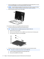
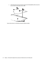
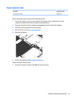
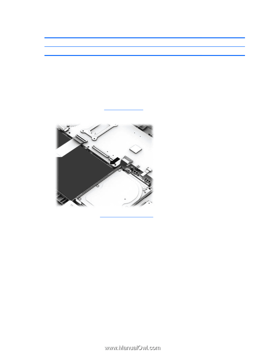
Power connector cable Description Power connector cable Spare part number 768012-001 Before removing the power connector cable, follow these steps: 1. Turn off the computer. If you are unsure whether the computer is off or in Hibernation, turn the computer on, and then shut it down through the operating system. 2. Disconnect the power from the computer by unplugging the power cord from the computer. 3. Disconnect all external devices from the computer. 4. Remove the top cover (see Top cover on page 28). 5. Disconnect the battery. 6. Remove the display (see Display assembly on page 53). Remove the power connector cable: 1. Disconnect the power connector cable (1) from the system board. Component replacement procedures 59
-
 1
1 -
2
-
3
-
4
-
5
-
6
-
7
-
8
-
9
-
10
-
11
-
12
-
13
-
14
-
15
-
16
-
17
-
18
-
19
-
20
-
21
-
22
-
23
-
24
-
25
-
26
-
27
-
28
-
29
-
30
-
31
-
32
-
33
-
34
-
35
-
36
-
37
-
38
-
39
-
40
-
41
-
42
-
43
-
44
-
45
-
46
-
47
-
48
-
49
-
50
-
51
-
52
-
53
-
54
-
55
-
56
-
57
-
58
-
59
-
60
-
61
-
 62
62 -
 63
63 -
 64
64 -
 65
65 -
 66
66 -
 67
67 -
 68
68 -
 69
69 -
 70
70 -
 71
71 -
 72
72 -
73
-
74
-
75
-
76
-
77
-
78
-
79
-
80
-
81
-
82
-
83
 |
 |
Power connector cable
Description
Spare part number
Power connector cable
768012-001
Before removing the power connector cable, follow these steps:
1.
Turn off the computer. If you are unsure whether the computer is off or in Hibernation, turn the
computer on, and then shut it down through the operating system.
2.
Disconnect the power from the computer by unplugging the power cord from the computer.
3.
Disconnect all external devices from the computer.
4.
Remove the top cover (see
Top cover
on page
28
).
5.
Disconnect the battery.
6.
Remove the display (see
Display assembly
on page
53
).
Remove the power connector cable:
1.
Disconnect the power connector cable
(1)
from the system board.
Component replacement procedures
59