HP ENVY 17-s000 Maintenance and Service Guide - Page 51
Heat sink
 |
View all HP ENVY 17-s000 manuals
Add to My Manuals
Save this manual to your list of manuals |
Page 51 highlights
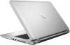
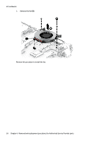
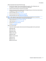
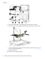
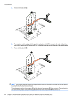
Heat sink NOTE: The heat sink spare part kit includes replacement thermal material. HP Confidential Description Spare part number For use only on computer models equipped with a graphics subsystem with dedicated video memory 806827-001 For use only on computer models equipped with a graphics subsystem with UMA memory and an Intel Core 806826-001 i7-6700HQ processor For use only on computer models equipped with a graphics subsystem with UMA memory and an Intel Core 828817-001 i7-6500U or Intel Core i5-6200U processor NOTE: To properly ventilate the computer, allow at least 7.6 cm (3.0 in) of clearance on the left side of the computer. The computer uses an electric fan for ventilation. The fan is controlled by a temperature sensor and is designed to turn on automatically when high temperature conditions exist. These conditions are affected by high external temperatures, system power consumption, power management/battery conservation configurations, battery fast charging, and software requirements. Exhaust air is displaced through the ventilation grill located on the left side of the computer. Before removing the heat sink, follow these steps: 1. Shut down the computer. If you are unsure whether the computer is off or in Hibernation, turn the computer on, and then shut it down through the operating system. 2. Disconnect all external devices connected to the computer. 3. Disconnect the power from the computer by first unplugging the power cord from the AC outlet and then unplugging the AC adapter from the computer. 4. Remove the battery (see Battery on page 24). 5. Remove the optical drive (see Optical drive on page 25). 6. Remove the bottom cover (see Bottom cover on page 28). 7. Remove the fan (see Fan on page 37). 8. Remove the system board (see System board on page 40). Remove the heat sink: 1. For computer models equipped with a graphics subsystem with discrete memory, in the order indicated, remove the six Phillips PM2.0×3.0 screws (1) that secure the heat sink to the system board. Component replacement procedures 43
-
 1
1 -
2
-
3
-
4
-
5
-
6
-
7
-
8
-
9
-
10
-
11
-
12
-
13
-
14
-
15
-
16
-
17
-
18
-
19
-
20
-
21
-
22
-
23
-
24
-
25
-
26
-
27
-
28
-
29
-
30
-
31
-
32
-
33
-
34
-
35
-
36
-
37
-
38
-
39
-
40
-
41
-
42
-
43
-
44
-
45
-
 46
46 -
 47
47 -
 48
48 -
 49
49 -
 50
50 -
 51
51 -
 52
52 -
 53
53 -
 54
54 -
 55
55 -
 56
56 -
57
-
58
-
59
-
60
-
61
-
62
-
63
-
64
-
65
-
66
-
67
-
68
-
69
-
70
-
71
-
72
-
73
-
74
-
75
-
76
-
77
-
78
-
79
-
80
-
81
-
82
 |
 |