HP ENVY 17-s000 Maintenance and Service Guide - Page 62
Remove the display back cover., If it is necessary to replace the display hinges
 |
View all HP ENVY 17-s000 manuals
Add to My Manuals
Save this manual to your list of manuals |
Page 62 highlights
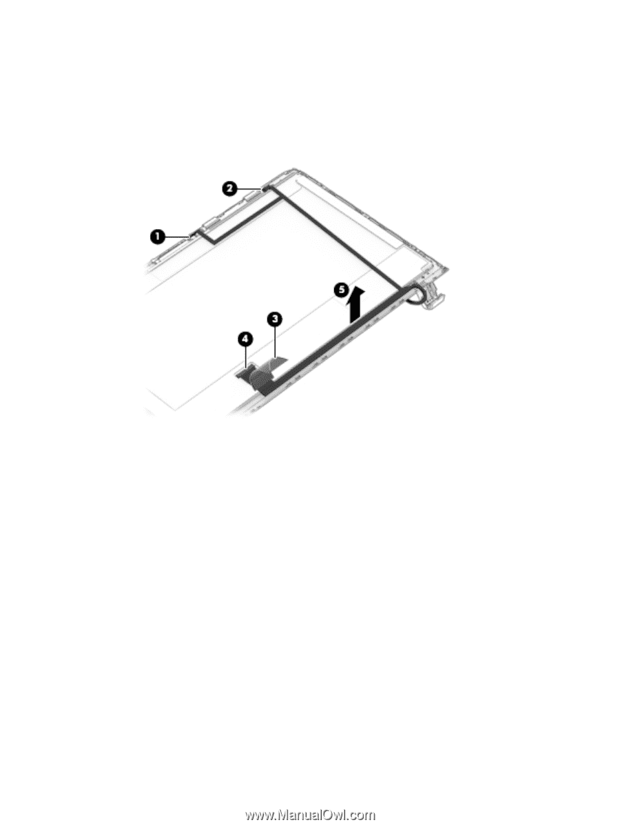
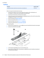
HP Confidential f. Release the display panel cable (5) from the display panel. (The display panel cable is attached to the display panel with double-sided adhesive.) The display panel cable includes the TouchScreen board cable and the webcam/microphone module cable and is available using spare part numbers 809294-001 (for use on computer models equipped with a TouchScreen display) and 847874-001 (for use on computer models equipped with a non-TouchScreen display). 7. If it is necessary to replace the display hinges: a. Remove the display back cover. b. Turn the display back cover right side up. c. Remove the six Phillips PM2.5×2.0 screws (1) and the two Phillips PM2.0×2.5 screws that secure the display hinges to the display back cover. 54 Chapter 6 Removal and replacement procedures for Authorized Service Provider parts
-
 1
1 -
2
-
3
-
4
-
5
-
6
-
7
-
8
-
9
-
10
-
11
-
12
-
13
-
14
-
15
-
16
-
17
-
18
-
19
-
20
-
21
-
22
-
23
-
24
-
25
-
26
-
27
-
28
-
29
-
30
-
31
-
32
-
33
-
34
-
35
-
36
-
37
-
38
-
39
-
40
-
41
-
42
-
43
-
44
-
45
-
46
-
47
-
48
-
49
-
50
-
51
-
52
-
53
-
54
-
55
-
56
-
 57
57 -
 58
58 -
 59
59 -
 60
60 -
 61
61 -
 62
62 -
 63
63 -
 64
64 -
 65
65 -
 66
66 -
 67
67 -
68
-
69
-
70
-
71
-
72
-
73
-
74
-
75
-
76
-
77
-
78
-
79
-
80
-
81
-
82
 |
 |