HP EliteBook 1000 Maintenance and Service Guide - Page 56
Display assembly
 |
View all HP EliteBook 1000 manuals
Add to My Manuals
Save this manual to your list of manuals |
Page 56 highlights
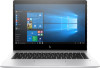
Display assembly Description LCD HU 14 FHD LED with WWAN capability, HDC infrared camera, touch screen, and privacy panel LCD HU 14 UHD LED with WWAN capability, HDC infrared camera, and touch screen LCD HU 14 FHD LED with UWVA HDC infrared camera, and touch screen LCD HU 14 FHD LED with WWAN capability, HDC infrared camera, and touch screen LCD HU 14 FHD AG LED with WWAN capability, HDC infrared camera, and privacy panel LCD HU 14 UHD AG LED with WWAN capability, HDC and infrared camera LCD HU 14 FHD AG LED, UWVA, HDC, with WWAN capability, and infrared camera LCD HU 14 FHD AG LED, UWVA, HDC, and infrared camera Spare part number L02254-001 L02256-001 L04869-001 L04870-001 L02253-001 L02255-001 L02257-001 L04868-001 IMPORTANT: Make special note of each screw and screw lock size and location during removal and replacement Before removing the display assembly, follow these steps: 1. Shut down the computer. 2. Disconnect all external devices connected to the computer. 3. Disconnect the power from the computer by first unplugging the power cord from the AC outlet and then unplugging the AC adapter from the computer. 4. Remove the base enclosure (see Base enclosure on page 34), and then remove the following components: a. Battery(see Battery on page 35). b. System board (see System board on page 41). c. Fingerprint reader (see Fingerprint reader on page 44). d. Remove the display assembly: ▲ Open the display (1), remove 2 M2.5*4.5 screws from the left hinge, and 1 2 M2.5*4.5 screw from the right hinge (2), and then slide the display assembly to remove it (3). 48 Chapter 5 Removal and replacement procedures for authorized service provider parts
-
 1
1 -
2
-
3
-
4
-
5
-
6
-
7
-
8
-
9
-
10
-
11
-
12
-
13
-
14
-
15
-
16
-
17
-
18
-
19
-
20
-
21
-
22
-
23
-
24
-
25
-
26
-
27
-
28
-
29
-
30
-
31
-
32
-
33
-
34
-
35
-
36
-
37
-
38
-
39
-
40
-
41
-
42
-
43
-
44
-
45
-
46
-
47
-
48
-
49
-
50
-
 51
51 -
 52
52 -
 53
53 -
 54
54 -
 55
55 -
 56
56 -
 57
57 -
 58
58 -
 59
59 -
 60
60 -
 61
61 -
62
-
63
-
64
-
65
-
66
-
67
-
68
-
69
-
70
-
71
-
72
-
73
-
74
-
75
-
76
-
77
-
78
-
79
-
80
-
81
-
82
-
83
-
84
-
85
-
86
-
87
-
88
-
89
 |
 |
