HP EliteBook 8570w HP EliteBook 8570w Mobile Workstation Maintenance and Servi - Page 117
RJ-45 connector cable
 |
View all HP EliteBook 8570w manuals
Add to My Manuals
Save this manual to your list of manuals |
Page 117 highlights
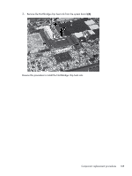
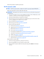
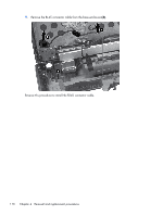
Reverse this procedure to install the system board. RJ-45 connector cable NOTE: The RJ-45 connector cable is included in the cable kit, spare part number 690623-001. Before removing the RJ-45 connector cable, follow these steps: IMPORTANT: Make special note of each screw and screw lock size and location during removal and replacement. 1. Shut down the computer. If you are unsure whether the computer is off or in Hibernation, turn the computer on, and then shut it down through the operating system. 2. Disconnect all external devices connected to the computer. 3. Disconnect the power from the computer by first unplugging the power cord from the AC outlet, and then unplugging the AC adapter from the computer. 4. Remove the battery (see Battery on page 46). 5. Remove the service door (see Service door on page 52). 6. Remove the following components: a. Hard drive (see Hard drive on page 63). b. Upgrade bay device (see Upgrade bay device on page 68). c. Keyboard (see Keyboard on page 72). d. Top cover (see Top cover on page 76). e. Fan and heat sink assembly (see Fan and heat sink assembly on page 89). f. Audio/USB 3.0 board (see Audio/USB 3.0 board on page 95). g. Speakers (see Speakers on page 99). h. ExpressCard/USB 2.0 assembly (see ExpressCard/USB 2.0 assembly on page 102). i. System board (see System board on page 106). Remove the RJ-45 connector cable: 1. Position the computer right-side up, with the front toward you. 2. Remove the tape (1) from the top of the RJ-45 connector cable. 3. Remove the RJ-45 connector cable from the clips and routing channel (2) built into the base enclosure. Component replacement procedures 109
-
 1
1 -
2
-
3
-
4
-
5
-
6
-
7
-
8
-
9
-
10
-
11
-
12
-
13
-
14
-
15
-
16
-
17
-
18
-
19
-
20
-
21
-
22
-
23
-
24
-
25
-
26
-
27
-
28
-
29
-
30
-
31
-
32
-
33
-
34
-
35
-
36
-
37
-
38
-
39
-
40
-
41
-
42
-
43
-
44
-
45
-
46
-
47
-
48
-
49
-
50
-
51
-
52
-
53
-
54
-
55
-
56
-
57
-
58
-
59
-
60
-
61
-
62
-
63
-
64
-
65
-
66
-
67
-
68
-
69
-
70
-
71
-
72
-
73
-
74
-
75
-
76
-
77
-
78
-
79
-
80
-
81
-
82
-
83
-
84
-
85
-
86
-
87
-
88
-
89
-
90
-
91
-
92
-
93
-
94
-
95
-
96
-
97
-
98
-
99
-
100
-
101
-
102
-
103
-
104
-
105
-
106
-
107
-
108
-
109
-
110
-
111
-
 112
112 -
 113
113 -
 114
114 -
 115
115 -
 116
116 -
 117
117 -
 118
118 -
 119
119 -
 120
120 -
 121
121 -
 122
122 -
123
-
124
-
125
-
126
-
127
-
128
-
129
-
130
-
131
-
132
-
133
-
134
-
135
-
136
-
137
-
138
-
139
-
140
-
141
-
142
-
143
-
144
-
145
-
146
-
147
-
148
-
149
-
150
-
151
-
152
-
153
-
154
-
155
-
156
-
157
-
158
-
159
-
160
-
161
-
162
-
163
-
164
-
165
-
166
-
167
 |
 |
