HP EliteBook 8570w HP EliteBook 8570w Mobile Workstation Maintenance and Servi - Page 95
VGA port board, Hard drive see - base system device
 |
View all HP EliteBook 8570w manuals
Add to My Manuals
Save this manual to your list of manuals |
Page 95 highlights
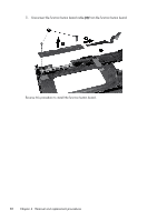
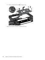
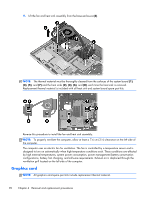
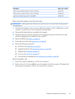
VGA port board Description VGA port board Spare part number 690641-001 Before removing the VGA port board, follow these steps: IMPORTANT: Make special note of each screw and screw lock size and location during removal and replacement. 1. Shut down the computer. If you are unsure whether the computer is off or in Hibernation, turn the computer on, and then shut it down through the operating system. 2. Disconnect all external devices connected to the computer. 3. Disconnect the power from the computer by first unplugging the power cord from the AC outlet, and then unplugging the AC adapter from the computer. 4. Remove the battery (see Battery on page 46). 5. Remove the service door (see Service door on page 52). 6. Remove the following components: a. Hard drive (see Hard drive on page 63). b. Upgrade bay device (see Upgrade bay device on page 68). c. Keyboard (see Keyboard on page 72). d. Top cover (see Top cover on page 76). Remove the VGA port board: 1. Position the computer right-side up with the front toward you. 2. Remove the Phillips screw (1) that secures the VGA port board to the base enclosure. 3. Remove the two Torx 8 screws (2) that secure the VGA port board to the base enclosure. Component replacement procedures 87
-
 1
1 -
2
-
3
-
4
-
5
-
6
-
7
-
8
-
9
-
10
-
11
-
12
-
13
-
14
-
15
-
16
-
17
-
18
-
19
-
20
-
21
-
22
-
23
-
24
-
25
-
26
-
27
-
28
-
29
-
30
-
31
-
32
-
33
-
34
-
35
-
36
-
37
-
38
-
39
-
40
-
41
-
42
-
43
-
44
-
45
-
46
-
47
-
48
-
49
-
50
-
51
-
52
-
53
-
54
-
55
-
56
-
57
-
58
-
59
-
60
-
61
-
62
-
63
-
64
-
65
-
66
-
67
-
68
-
69
-
70
-
71
-
72
-
73
-
74
-
75
-
76
-
77
-
78
-
79
-
80
-
81
-
82
-
83
-
84
-
85
-
86
-
87
-
88
-
89
-
 90
90 -
 91
91 -
 92
92 -
 93
93 -
 94
94 -
 95
95 -
 96
96 -
 97
97 -
 98
98 -
 99
99 -
 100
100 -
101
-
102
-
103
-
104
-
105
-
106
-
107
-
108
-
109
-
110
-
111
-
112
-
113
-
114
-
115
-
116
-
117
-
118
-
119
-
120
-
121
-
122
-
123
-
124
-
125
-
126
-
127
-
128
-
129
-
130
-
131
-
132
-
133
-
134
-
135
-
136
-
137
-
138
-
139
-
140
-
141
-
142
-
143
-
144
-
145
-
146
-
147
-
148
-
149
-
150
-
151
-
152
-
153
-
154
-
155
-
156
-
157
-
158
-
159
-
160
-
161
-
162
-
163
-
164
-
165
-
166
-
167
 |
 |
