HP EliteBook 8570w HP EliteBook 8570w Mobile Workstation Maintenance and Servi - Page 61
Memory Modules (under service door), Remove the service door see - remove keyboard
 |
View all HP EliteBook 8570w manuals
Add to My Manuals
Save this manual to your list of manuals |
Page 61 highlights
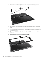
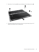
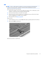
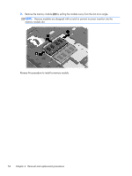
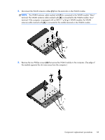
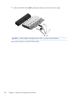
Memory Modules (under service door) NOTE: A computer having a system board with spare part number 690643-001 or 696441-001 has four memory slots. In this case, the primary memory is located under the keyboard and expansion memory is located under the service door. A computer having a system board with spare part number 690642-001 or 696440-001 has two memory module slots. In this case, the primary memory is located under the service door. To access memory modules under the keyboard, see Memory Modules (under keyboard) on page 74. Description 8 GB (DDR3 1600MHz PC3-12800) 4 GB (DDR3 1600MHz PC3-12800) 2 GB (DDR3 1600MHz PC3-12800) Spare part number 670034-001 641369-001 652972-001 Before removing a memory module, follow these steps: 1. Shut down the computer. If you are unsure whether the computer is off or in Hibernation, turn the computer on, and then shut it down through the operating system. 2. Disconnect all external devices connected to the computer. 3. Disconnect the power from the computer by first unplugging the power cord from the AC outlet, and then unplugging the AC adapter from the computer. 4. Remove the battery (see Battery on page 46). 5. Remove the service door (see Service door on page 52). Remove the memory module: 1. Position the computer upside down, with the front toward you. 2. Spread the retaining tabs (1) on each side of the memory module slot to release the memory module. (The edge of the module opposite the slot rises away from the computer.) Component replacement procedures 53
-
 1
1 -
2
-
3
-
4
-
5
-
6
-
7
-
8
-
9
-
10
-
11
-
12
-
13
-
14
-
15
-
16
-
17
-
18
-
19
-
20
-
21
-
22
-
23
-
24
-
25
-
26
-
27
-
28
-
29
-
30
-
31
-
32
-
33
-
34
-
35
-
36
-
37
-
38
-
39
-
40
-
41
-
42
-
43
-
44
-
45
-
46
-
47
-
48
-
49
-
50
-
51
-
52
-
53
-
54
-
55
-
 56
56 -
 57
57 -
 58
58 -
 59
59 -
 60
60 -
 61
61 -
 62
62 -
 63
63 -
 64
64 -
 65
65 -
 66
66 -
67
-
68
-
69
-
70
-
71
-
72
-
73
-
74
-
75
-
76
-
77
-
78
-
79
-
80
-
81
-
82
-
83
-
84
-
85
-
86
-
87
-
88
-
89
-
90
-
91
-
92
-
93
-
94
-
95
-
96
-
97
-
98
-
99
-
100
-
101
-
102
-
103
-
104
-
105
-
106
-
107
-
108
-
109
-
110
-
111
-
112
-
113
-
114
-
115
-
116
-
117
-
118
-
119
-
120
-
121
-
122
-
123
-
124
-
125
-
126
-
127
-
128
-
129
-
130
-
131
-
132
-
133
-
134
-
135
-
136
-
137
-
138
-
139
-
140
-
141
-
142
-
143
-
144
-
145
-
146
-
147
-
148
-
149
-
150
-
151
-
152
-
153
-
154
-
155
-
156
-
157
-
158
-
159
-
160
-
161
-
162
-
163
-
164
-
165
-
166
-
167
 |
 |
