HP Evo n410c Compaq Evo N400c and N410c Notebook PCs - Maintenance and Service - Page 87
Disassembly Sequence Chart
 |
View all HP Evo n410c manuals
Add to My Manuals
Save this manual to your list of manuals |
Page 87 highlights
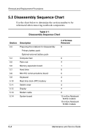
Removal and Replacement Procedures 5.2 Disassembly Sequence Chart Use the chart below to determine the section number to be referenced when removing notebook components. Table 5-1 Disassembly Sequence Chart Section 5.3 5.4 5.5 5.6 5.7 5.8 5.9 5.10 5.11 5.12 5.13 5.14 Description Preparing the notebook for disassembly Primary battery pack Optional external battery pack Computer feet Palm rest Memory expansion board Hard drive Mini PCI communications board Keyboard Real time clock (RTC) battery Switch cover Display Modem cable System board # of Screws Removed 0 0 4 1 0 0 4 0 4 4 2 12 on Evo Notebook N410c models 10 on Evo Notebook N400c models 5-2 Maintenance and Service Guide
-
 1
1 -
2
-
3
-
4
-
5
-
6
-
7
-
8
-
9
-
10
-
11
-
12
-
13
-
14
-
15
-
16
-
17
-
18
-
19
-
20
-
21
-
22
-
23
-
24
-
25
-
26
-
27
-
28
-
29
-
30
-
31
-
32
-
33
-
34
-
35
-
36
-
37
-
38
-
39
-
40
-
41
-
42
-
43
-
44
-
45
-
46
-
47
-
48
-
49
-
50
-
51
-
52
-
53
-
54
-
55
-
56
-
57
-
58
-
59
-
60
-
61
-
62
-
63
-
64
-
65
-
66
-
67
-
68
-
69
-
70
-
71
-
72
-
73
-
74
-
75
-
76
-
77
-
78
-
79
-
80
-
81
-
 82
82 -
 83
83 -
 84
84 -
 85
85 -
 86
86 -
 87
87 -
 88
88 -
 89
89 -
 90
90 -
 91
91 -
 92
92 -
93
-
94
-
95
-
96
-
97
-
98
-
99
-
100
-
101
-
102
-
103
-
104
-
105
-
106
-
107
-
108
-
109
-
110
-
111
-
112
-
113
-
114
-
115
-
116
-
117
-
118
-
119
-
120
-
121
-
122
-
123
-
124
-
125
-
126
-
127
-
128
-
129
-
130
-
131
-
132
-
133
-
134
-
135
-
136
-
137
-
138
-
139
-
140
-
141
-
142
-
143
-
144
-
145
-
146
-
147
-
148
-
149
-
150
-
151
-
152
-
153
-
154
-
155
-
156
-
157
-
158
-
159
-
160
-
161
-
162
-
163
-
164
-
165
-
166
-
167
-
168
-
169
-
170
-
171
 |
 |
5–2
Maintenance and Service Guide
Removal and Replacement Procedures
5.2 Disassembly Sequence Chart
Use the chart below to determine the section number to be
referenced when removing notebook components.
Table 5-1
Disassembly Sequence Chart
Section
Description
# of Screws
Removed
5.3
Preparing the notebook for disassembly
0
Primary battery pack
Optional external battery pack
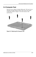
5.4
Computer feet
0
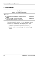
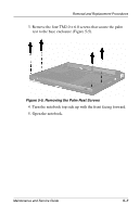
5.5
Palm rest
4
5.6
Memory expansion board
1
5.7
Hard drive
0
5.8
Mini PCI communications board
0
5.9
Keyboard
4
5.10
Real time clock (RTC) battery
0
5.11
Switch cover
4
5.12
Display
4
5.13
Modem cable
2
5.14
System board
12 on Evo Notebook
N410c models
10 on Evo Notebook
N400c models