HP G62-229NR Service Guide - Page 81
it to the system board., from the system board and release it from the clips that attach
 |
View all HP G62-229NR manuals
Add to My Manuals
Save this manual to your list of manuals |
Page 81 highlights
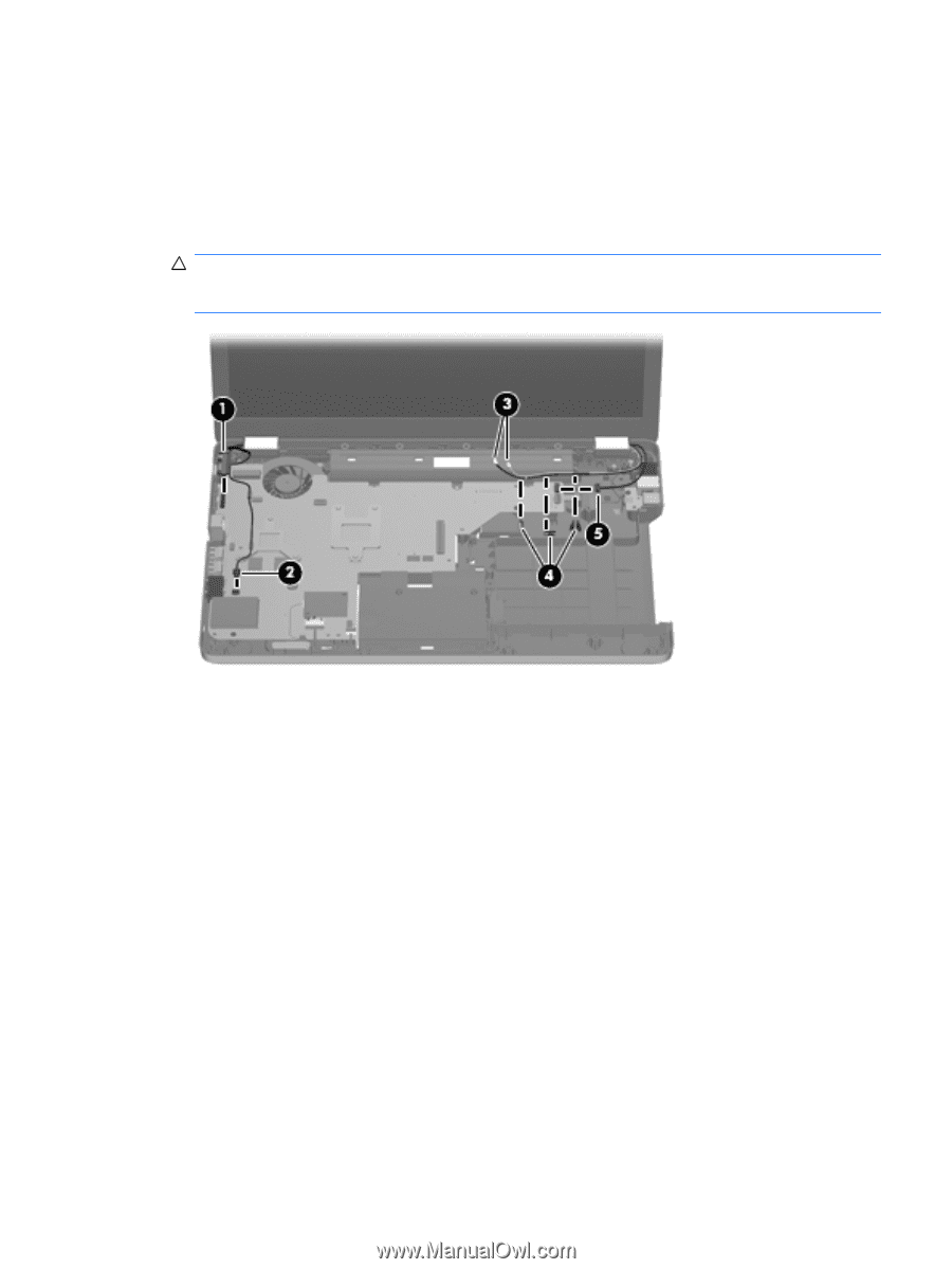
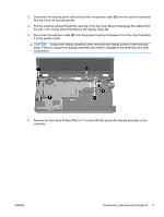
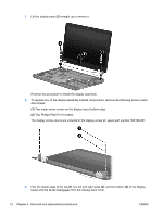
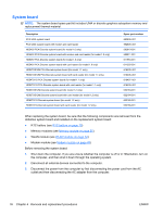
3. Disconnect the display panel cable (1) and the microphone cable (2) from the system board and remove it from its routing channel. 4. Pull the antenna cables through the opening in the top cover (3) and disengage the cables from the clip in the routing channel leading to the display hinge (4). 5. Disconnect the webcam cable (5) from the system board and release it from the clips that attach it to the system board. CAUTION: Support the display assembly when removing the display screws in the following steps. Failure to support the display assembly can result in damage to the assembly and other components. 6. Remove the four black Phillips PM2.5×7.0 screws (1) that secure the display assembly to the computer. ENWW Component replacement procedures 71
-
 1
1 -
2
-
3
-
4
-
5
-
6
-
7
-
8
-
9
-
10
-
11
-
12
-
13
-
14
-
15
-
16
-
17
-
18
-
19
-
20
-
21
-
22
-
23
-
24
-
25
-
26
-
27
-
28
-
29
-
30
-
31
-
32
-
33
-
34
-
35
-
36
-
37
-
38
-
39
-
40
-
41
-
42
-
43
-
44
-
45
-
46
-
47
-
48
-
49
-
50
-
51
-
52
-
53
-
54
-
55
-
56
-
57
-
58
-
59
-
60
-
61
-
62
-
63
-
64
-
65
-
66
-
67
-
68
-
69
-
70
-
71
-
72
-
73
-
74
-
75
-
 76
76 -
 77
77 -
 78
78 -
 79
79 -
 80
80 -
 81
81 -
 82
82 -
 83
83 -
 84
84 -
 85
85 -
 86
86 -
87
-
88
-
89
-
90
-
91
-
92
-
93
-
94
-
95
-
96
-
97
-
98
-
99
-
100
-
101
-
102
-
103
-
104
-
105
-
106
-
107
-
108
-
109
-
110
-
111
-
112
-
113
-
114
-
115
-
116
-
117
-
118
-
119
-
120
-
121
-
122
-
123
-
124
-
125
-
126
-
127
-
128
-
129
-
130
-
131
-
132
-
133
-
134
-
135
-
136
-
137
-
138
-
139
-
140
-
141
-
142
-
143
-
144
-
145
-
146
 |
 |