HP G62-229NR Service Guide - Page 87
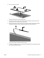
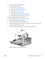
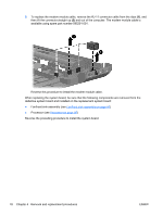
Remove the three Phillips PM2.5×4.0, screws that secure the system board to the computer.
 |
View all HP G62-229NR manuals
Add to My Manuals
Save this manual to your list of manuals |
Page 87 highlights
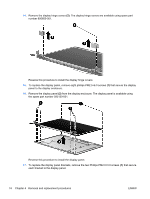
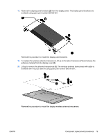
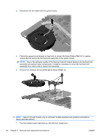
4. Remove the battery (see Battery on page 46). 5. Remove the following components: a. Hard drive (see Hard drive on page 47) b. Optical drive (see Optical drive on page 50) c. Keyboard (see Keyboard on page 57) d. Top cover (see Top cover on page 59) e. Speaker assembly (see Speaker assembly on page 62) f. Display assembly (see Display assembly on page 70) Remove the following cables from the system board: ● Power connector cable (see Power connector on page 69) ● USB board cable (see USB board on page 67) 1. Turn the computer upright with the right side toward you. 2. Remove the three Phillips PM2.5×4.0 (1) screws that secure the system board to the computer. 3. Grasp the right edge (2) of the system board. 4. Lift the system board (3), and pull it away from the base enclosure at an angle. Reverse this procedure to install the system board. ENWW Component replacement procedures 77
-
 1
1 -
2
-
3
-
4
-
5
-
6
-
7
-
8
-
9
-
10
-
11
-
12
-
13
-
14
-
15
-
16
-
17
-
18
-
19
-
20
-
21
-
22
-
23
-
24
-
25
-
26
-
27
-
28
-
29
-
30
-
31
-
32
-
33
-
34
-
35
-
36
-
37
-
38
-
39
-
40
-
41
-
42
-
43
-
44
-
45
-
46
-
47
-
48
-
49
-
50
-
51
-
52
-
53
-
54
-
55
-
56
-
57
-
58
-
59
-
60
-
61
-
62
-
63
-
64
-
65
-
66
-
67
-
68
-
69
-
70
-
71
-
72
-
73
-
74
-
75
-
76
-
77
-
78
-
79
-
80
-
81
-
 82
82 -
 83
83 -
 84
84 -
 85
85 -
 86
86 -
 87
87 -
 88
88 -
 89
89 -
 90
90 -
 91
91 -
 92
92 -
93
-
94
-
95
-
96
-
97
-
98
-
99
-
100
-
101
-
102
-
103
-
104
-
105
-
106
-
107
-
108
-
109
-
110
-
111
-
112
-
113
-
114
-
115
-
116
-
117
-
118
-
119
-
120
-
121
-
122
-
123
-
124
-
125
-
126
-
127
-
128
-
129
-
130
-
131
-
132
-
133
-
134
-
135
-
136
-
137
-
138
-
139
-
140
-
141
-
142
-
143
-
144
-
145
-
146
 |
 |