HP G62-229NR Service Guide - Page 82
Two Phillips PM2.5×4.0 screws, the left and right sides
 |
View all HP G62-229NR manuals
Add to My Manuals
Save this manual to your list of manuals |
Page 82 highlights
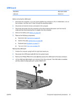
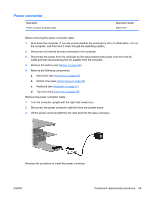
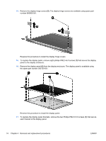
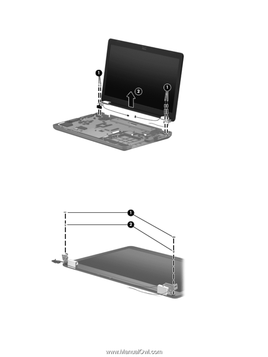
7. Lift the display panel (2) straight up to remove it. Reverse this procedure to install the display assembly. 8. To replace any of the display assembly internal components, remove the following screw covers and screws: (1) Two mylar screw covers on the display bezel bottom edge (2) Two Phillips PM2.5×4.0 screws The display screw covers are included in the display screw kit, spare part number 595198-001. 9. Flex the inside edge of the top (1), the left and right sides (2), and the bottom (3) of the display bezel until the bezel disengages from the display back cover. 72 Chapter 4 Removal and replacement procedures ENWW
-
 1
1 -
2
-
3
-
4
-
5
-
6
-
7
-
8
-
9
-
10
-
11
-
12
-
13
-
14
-
15
-
16
-
17
-
18
-
19
-
20
-
21
-
22
-
23
-
24
-
25
-
26
-
27
-
28
-
29
-
30
-
31
-
32
-
33
-
34
-
35
-
36
-
37
-
38
-
39
-
40
-
41
-
42
-
43
-
44
-
45
-
46
-
47
-
48
-
49
-
50
-
51
-
52
-
53
-
54
-
55
-
56
-
57
-
58
-
59
-
60
-
61
-
62
-
63
-
64
-
65
-
66
-
67
-
68
-
69
-
70
-
71
-
72
-
73
-
74
-
75
-
76
-
 77
77 -
 78
78 -
 79
79 -
 80
80 -
 81
81 -
 82
82 -
 83
83 -
 84
84 -
 85
85 -
 86
86 -
 87
87 -
88
-
89
-
90
-
91
-
92
-
93
-
94
-
95
-
96
-
97
-
98
-
99
-
100
-
101
-
102
-
103
-
104
-
105
-
106
-
107
-
108
-
109
-
110
-
111
-
112
-
113
-
114
-
115
-
116
-
117
-
118
-
119
-
120
-
121
-
122
-
123
-
124
-
125
-
126
-
127
-
128
-
129
-
130
-
131
-
132
-
133
-
134
-
135
-
136
-
137
-
138
-
139
-
140
-
141
-
142
-
143
-
144
-
145
-
146
 |
 |
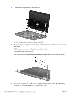
7.
Lift the display panel
(2)
straight up to remove it.
Reverse this procedure to install the display assembly.
8.
To replace any of the display assembly internal components, remove the following screw covers
and screws:
(1)
Two mylar screw covers on the display bezel bottom edge
(2)
Two Phillips PM2.5×4.0 screws
The display screw covers are included in the display screw kit, spare part number 595198-001.
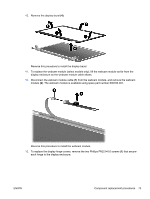
9.
Flex the inside edge of the top
(1)
, the left and right sides
(2)
, and the bottom
(3)
of the display
bezel until the bezel disengages from the display back cover.
72
Chapter 4
Removal and replacement procedures
ENWW