HP G62-229NR Service Guide - Page 94
and the processor component
 |
View all HP G62-229NR manuals
Add to My Manuals
Save this manual to your list of manuals |
Page 94 highlights
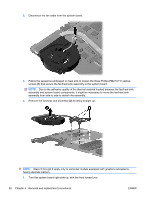
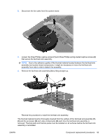
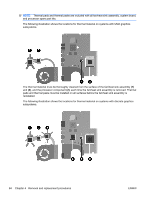
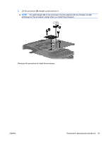
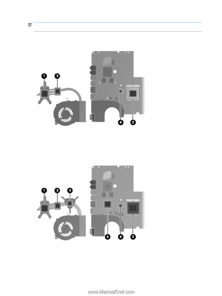
NOTE: Thermal pads and thermal paste are included with all fan/heat sink assembly, system board, and processor spare part kits. The following illustration shows the locations for thermal material on systems with UMA graphics subsystems. The thermal material must be thoroughly cleaned from the surface of the fan/heat sink assembly (1) and (3), and the processor component (2), each time the fan/heat sink assembly is removed. Thermal pads and thermal paste must be installed on all surfaces before the fan/heat sink assembly is reinstalled. The following illustration shows the locations for thermal material on systems with discrete graphics subsystems. 84 Chapter 4 Removal and replacement procedures ENWW
-
 1
1 -
2
-
3
-
4
-
5
-
6
-
7
-
8
-
9
-
10
-
11
-
12
-
13
-
14
-
15
-
16
-
17
-
18
-
19
-
20
-
21
-
22
-
23
-
24
-
25
-
26
-
27
-
28
-
29
-
30
-
31
-
32
-
33
-
34
-
35
-
36
-
37
-
38
-
39
-
40
-
41
-
42
-
43
-
44
-
45
-
46
-
47
-
48
-
49
-
50
-
51
-
52
-
53
-
54
-
55
-
56
-
57
-
58
-
59
-
60
-
61
-
62
-
63
-
64
-
65
-
66
-
67
-
68
-
69
-
70
-
71
-
72
-
73
-
74
-
75
-
76
-
77
-
78
-
79
-
80
-
81
-
82
-
83
-
84
-
85
-
86
-
87
-
88
-
 89
89 -
 90
90 -
 91
91 -
 92
92 -
 93
93 -
 94
94 -
 95
95 -
 96
96 -
 97
97 -
 98
98 -
 99
99 -
100
-
101
-
102
-
103
-
104
-
105
-
106
-
107
-
108
-
109
-
110
-
111
-
112
-
113
-
114
-
115
-
116
-
117
-
118
-
119
-
120
-
121
-
122
-
123
-
124
-
125
-
126
-
127
-
128
-
129
-
130
-
131
-
132
-
133
-
134
-
135
-
136
-
137
-
138
-
139
-
140
-
141
-
142
-
143
-
144
-
145
-
146
 |
 |
NOTE:
Thermal pads and thermal paste are included with all fan/heat sink assembly, system board,
and processor spare part kits.
The following illustration shows the locations for thermal material on systems with UMA graphics
subsystems.
The thermal material must be thoroughly cleaned from the surface of the fan/heat sink assembly
(1)
and
(3)
, and the processor component
(2)
, each time the fan/heat sink assembly is removed. Thermal
pads and thermal paste must be installed on all surfaces before the fan/heat sink assembly is
reinstalled.
The following illustration shows the locations for thermal material on systems with discrete graphics
subsystems.
84
Chapter 4
Removal and replacement procedures
ENWW