HP G62-229NR Service Guide - Page 91
Fan/heat sink assembly, Keyboard see
 |
View all HP G62-229NR manuals
Add to My Manuals
Save this manual to your list of manuals |
Page 91 highlights
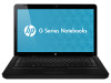
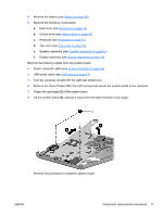
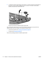
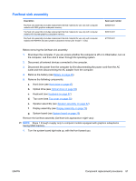
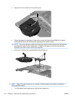
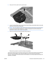
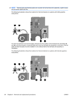
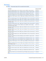
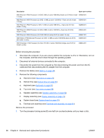
Fan/heat sink assembly Description Fan/heat sink assembly (includes replacement thermal material) for use only with computer models with UMA graphics subsystem memory Fan/heat sink assembly (includes replacement thermal material) for use only with computer models with discrete graphics subsystem memory Fan/heat sink assembly (includes replacement thermal material) for use only with computer models with HD545V discrete systems subsystem memory (for model 1.1 only) Spare part number 606609-001 606610-001 617029-001 Before removing the fan/heat sink assembly: 1. Shut down the computer. If you are unsure whether the computer is off or in Hibernation, turn on the computer, and then shut it down through the operating system. 2. Disconnect all external devices connected to the computer. 3. Disconnect the power from the computer by first disconnecting the power cord from the AC outlet and then disconnecting the AC adapter from the computer. 4. Remove the battery (see Battery on page 46). 5. Remove the following components: a. Hard drive (see Hard drive on page 47) b. Optical drive (see Optical drive on page 50) c. Keyboard (see Keyboard on page 57) d. Top cover (see Top cover on page 59) e. Speaker assembly (see Speaker assembly on page 62) f. Display assembly (see Display assembly on page 70) g. System board (see System board on page 76) Remove the fan/heat assembly (fan/heat sink appearance might vary): NOTE: Steps 1 through 4 apply only to computer models equipped with graphics subsystems having UMA memory. 1. Turn the system board right-side up, with the front toward you. ENWW Component replacement procedures 81
-
 1
1 -
2
-
3
-
4
-
5
-
6
-
7
-
8
-
9
-
10
-
11
-
12
-
13
-
14
-
15
-
16
-
17
-
18
-
19
-
20
-
21
-
22
-
23
-
24
-
25
-
26
-
27
-
28
-
29
-
30
-
31
-
32
-
33
-
34
-
35
-
36
-
37
-
38
-
39
-
40
-
41
-
42
-
43
-
44
-
45
-
46
-
47
-
48
-
49
-
50
-
51
-
52
-
53
-
54
-
55
-
56
-
57
-
58
-
59
-
60
-
61
-
62
-
63
-
64
-
65
-
66
-
67
-
68
-
69
-
70
-
71
-
72
-
73
-
74
-
75
-
76
-
77
-
78
-
79
-
80
-
81
-
82
-
83
-
84
-
85
-
 86
86 -
 87
87 -
 88
88 -
 89
89 -
 90
90 -
 91
91 -
 92
92 -
 93
93 -
 94
94 -
 95
95 -
 96
96 -
97
-
98
-
99
-
100
-
101
-
102
-
103
-
104
-
105
-
106
-
107
-
108
-
109
-
110
-
111
-
112
-
113
-
114
-
115
-
116
-
117
-
118
-
119
-
120
-
121
-
122
-
123
-
124
-
125
-
126
-
127
-
128
-
129
-
130
-
131
-
132
-
133
-
134
-
135
-
136
-
137
-
138
-
139
-
140
-
141
-
142
-
143
-
144
-
145
-
146
 |
 |