HP G62-400 HP G62 Notebook PC - Maintenance and Service Guide - Page 78
Display assembly, Turn the computer display-side up, with the front toward you.
 |
View all HP G62-400 manuals
Add to My Manuals
Save this manual to your list of manuals |
Page 78 highlights
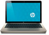
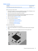
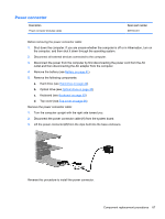
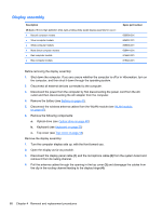
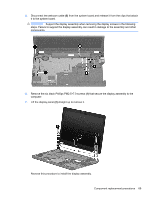
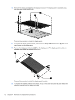
Display assembly Description 39.6-cm (15.6-in) High Definition (HD), light-emitting diode (LED) display assembly for use in: ● Biscotti computer models ● Silver computer models ● White computer models ● Matte black computer models ● Red computer models ● Blue computer models Spare part number 605906-001 605907-001 605908-001 608444-001 615423-001 615424-001 Before removing the display assembly: 1. Shut down the computer. If you are unsure whether the computer is off or in Hibernation, turn on the computer, and then shut it down through the operating system. 2. Disconnect all external devices connected to the computer. 3. Disconnect the power from the computer by first disconnecting the power cord from the AC outlet and then disconnecting the AC adapter from the computer. 4. Remove the battery (see Battery on page 41). 5. Disconnect the wireless antenna cables from the WLAN module (see WLAN module on page 47). 6. Remove the following components: a. Optical drive (see Optical drive on page 45) b. Keyboard (see Keyboard on page 53) c. Top cover (see Top cover on page 56) Remove the display assembly: 1. Turn the computer display-side up, with the front toward you. 2. Open the display as far as possible. 3. Disconnect the display panel cable (1) and the microphone cable (2) from the system board and remove it from its routing channel. 4. Pull the antenna cables through the opening in the top cover (3) and disengage the cables from the clip in the routing channel leading to the display hinge (4). 68 Chapter 4 Removal and replacement procedures
-
 1
1 -
2
-
3
-
4
-
5
-
6
-
7
-
8
-
9
-
10
-
11
-
12
-
13
-
14
-
15
-
16
-
17
-
18
-
19
-
20
-
21
-
22
-
23
-
24
-
25
-
26
-
27
-
28
-
29
-
30
-
31
-
32
-
33
-
34
-
35
-
36
-
37
-
38
-
39
-
40
-
41
-
42
-
43
-
44
-
45
-
46
-
47
-
48
-
49
-
50
-
51
-
52
-
53
-
54
-
55
-
56
-
57
-
58
-
59
-
60
-
61
-
62
-
63
-
64
-
65
-
66
-
67
-
68
-
69
-
70
-
71
-
72
-
 73
73 -
 74
74 -
 75
75 -
 76
76 -
 77
77 -
 78
78 -
 79
79 -
 80
80 -
 81
81 -
 82
82 -
 83
83 -
84
-
85
-
86
-
87
-
88
-
89
-
90
-
91
-
92
-
93
-
94
-
95
-
96
-
97
-
98
-
99
-
100
-
101
-
102
-
103
-
104
-
105
-
106
-
107
-
108
-
109
-
110
-
111
-
112
-
113
-
114
-
115
-
116
-
117
-
118
-
119
-
120
-
121
-
122
-
123
-
124
-
125
-
126
-
127
-
128
-
129
-
130
-
131
-
132
-
133
-
134
-
135
 |
 |