HP G62-400 HP G62 Notebook PC - Maintenance and Service Guide - Page 84
System board, Remove the following components
 |
View all HP G62-400 manuals
Add to My Manuals
Save this manual to your list of manuals |
Page 84 highlights
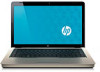
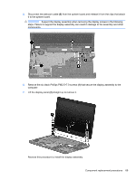
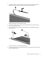
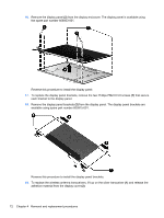
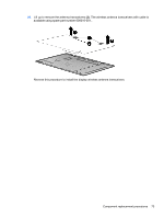
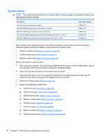
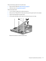
System board NOTE: The system board spare part kit includes UMA or discrete graphics subsystem memory and replacement thermal material. Description HD UMA system board with card reader HD 5470/512 MB discrete system board with card reader HD 5470/1 GB discrete system board with card reader HD 5470/ 512 MB discrete system board with card reader (for model 1.1 only) HD 5470/1 GB discrete system board with card reader (for model 1.1 only) Spare part number 605903-001 605902-001 608340-001 615381-001 615382-001 When replacing the system board, be sure that the following components are removed from the defective system board and installed on the replacement system board: ● Memory modules (see Memory module on page 50) ● WLAN module (see WLAN module on page 47) ● Modem module (see Modem module on page 63) Before removing the system board: 1. Shut down the computer. If you are unsure whether the computer is off or in Hibernation, turn on the computer, and then shut it down through the operating system. 2. Disconnect all external devices connected to the computer. 3. Disconnect the power from the computer by first disconnecting the power cord from the AC outlet and then disconnecting the AC adapter from the computer. 4. Remove the battery (see Battery on page 41). 5. Remove the following components: a. Hard drive (see Hard drive on page 42) b. Optical drive (see Optical drive on page 45) c. WLAN module (see WLAN module on page 47) d. Memory module (see Memory module on page 50) e. Keyboard (see Keyboard on page 53) f. Top cover (see Top cover on page 56) g. Modem module (see Modem module on page 63) h. Display assembly (see Display assembly on page 68) 74 Chapter 4 Removal and replacement procedures
-
 1
1 -
2
-
3
-
4
-
5
-
6
-
7
-
8
-
9
-
10
-
11
-
12
-
13
-
14
-
15
-
16
-
17
-
18
-
19
-
20
-
21
-
22
-
23
-
24
-
25
-
26
-
27
-
28
-
29
-
30
-
31
-
32
-
33
-
34
-
35
-
36
-
37
-
38
-
39
-
40
-
41
-
42
-
43
-
44
-
45
-
46
-
47
-
48
-
49
-
50
-
51
-
52
-
53
-
54
-
55
-
56
-
57
-
58
-
59
-
60
-
61
-
62
-
63
-
64
-
65
-
66
-
67
-
68
-
69
-
70
-
71
-
72
-
73
-
74
-
75
-
76
-
77
-
78
-
 79
79 -
 80
80 -
 81
81 -
 82
82 -
 83
83 -
 84
84 -
 85
85 -
 86
86 -
 87
87 -
 88
88 -
 89
89 -
90
-
91
-
92
-
93
-
94
-
95
-
96
-
97
-
98
-
99
-
100
-
101
-
102
-
103
-
104
-
105
-
106
-
107
-
108
-
109
-
110
-
111
-
112
-
113
-
114
-
115
-
116
-
117
-
118
-
119
-
120
-
121
-
122
-
123
-
124
-
125
-
126
-
127
-
128
-
129
-
130
-
131
-
132
-
133
-
134
-
135
 |
 |