HP G62-400 HP G62 Notebook PC - Maintenance and Service Guide - Page 86
Fan/heat sink assembly see, When replacing the system board
 |
View all HP G62-400 manuals
Add to My Manuals
Save this manual to your list of manuals |
Page 86 highlights
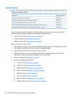
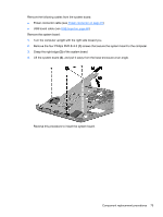
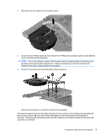
5. To replace the modem module cable, remove the RJ-11 connector cable from the clips (1), and then lift the connector straight up (2) and out of the computer. The modem module cable is available with the cable kit using spare part number 606009-001. Reverse this procedure to install the modem module cable. When replacing the system board, be sure that the following components are removed from the defective system board and installed on the replacement system board: ● Fan/heat sink assembly (see Fan/heat sink assembly on page 77) ● Processor (see Processor on page 81) Reverse the preceding procedure to install the system board. 76 Chapter 4 Removal and replacement procedures
-
 1
1 -
2
-
3
-
4
-
5
-
6
-
7
-
8
-
9
-
10
-
11
-
12
-
13
-
14
-
15
-
16
-
17
-
18
-
19
-
20
-
21
-
22
-
23
-
24
-
25
-
26
-
27
-
28
-
29
-
30
-
31
-
32
-
33
-
34
-
35
-
36
-
37
-
38
-
39
-
40
-
41
-
42
-
43
-
44
-
45
-
46
-
47
-
48
-
49
-
50
-
51
-
52
-
53
-
54
-
55
-
56
-
57
-
58
-
59
-
60
-
61
-
62
-
63
-
64
-
65
-
66
-
67
-
68
-
69
-
70
-
71
-
72
-
73
-
74
-
75
-
76
-
77
-
78
-
79
-
80
-
 81
81 -
 82
82 -
 83
83 -
 84
84 -
 85
85 -
 86
86 -
 87
87 -
 88
88 -
 89
89 -
 90
90 -
 91
91 -
92
-
93
-
94
-
95
-
96
-
97
-
98
-
99
-
100
-
101
-
102
-
103
-
104
-
105
-
106
-
107
-
108
-
109
-
110
-
111
-
112
-
113
-
114
-
115
-
116
-
117
-
118
-
119
-
120
-
121
-
122
-
123
-
124
-
125
-
126
-
127
-
128
-
129
-
130
-
131
-
132
-
133
-
134
-
135
 |
 |
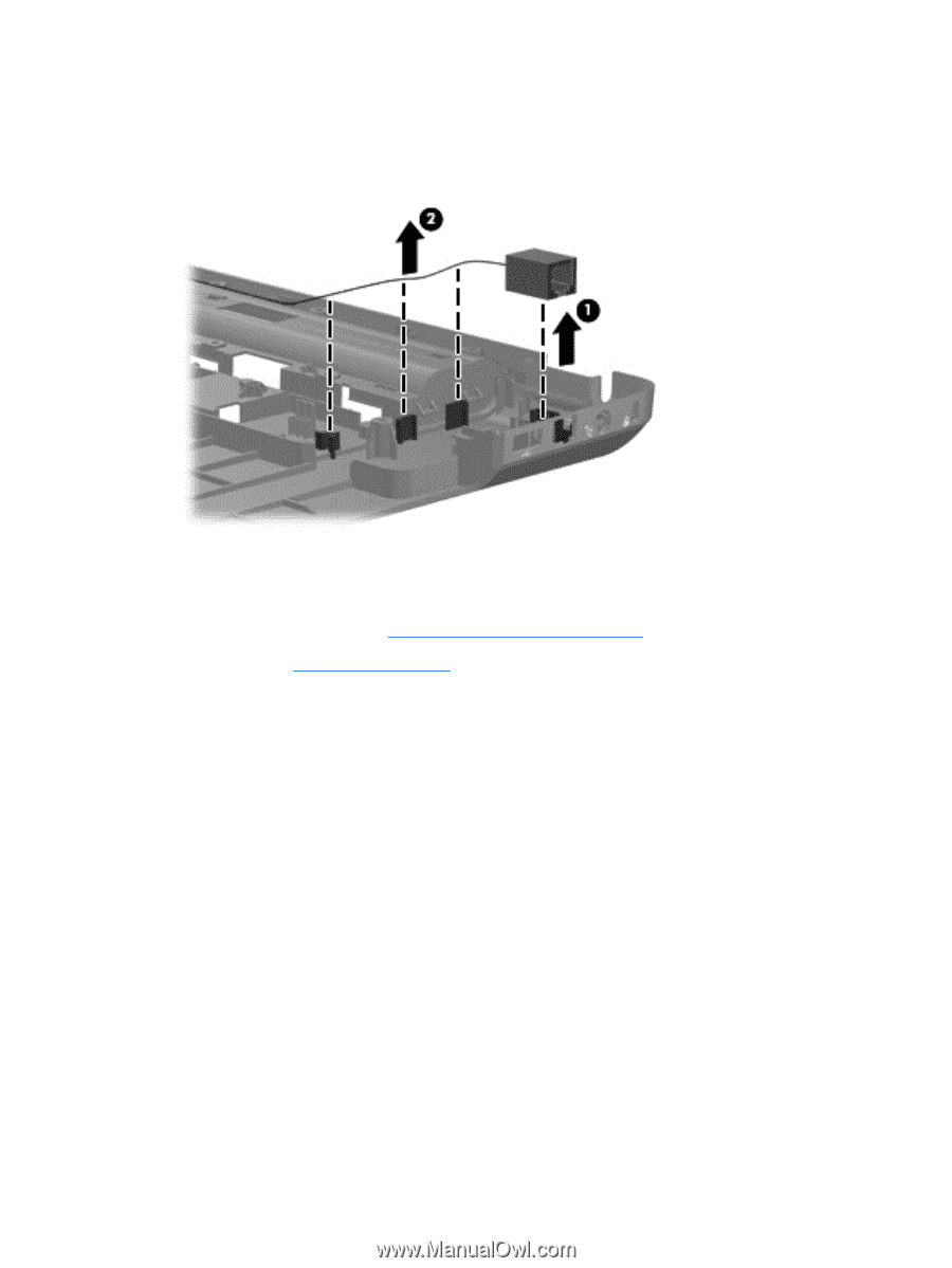
5.
To replace the modem module cable, remove the RJ-11 connector cable from the clips
(1)
, and
then lift the connector straight up
(2)
and out of the computer. The modem module cable is
available with the cable kit using spare part number 606009-001.
Reverse this procedure to install the modem module cable.
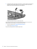
When replacing the system board, be sure that the following components are removed from the
defective system board and installed on the replacement system board:
●
Fan/heat sink assembly (see
Fan/heat sink assembly
on page
77
)
●
Processor (see
Processor
on page
81
)
Reverse the preceding procedure to install the system board.
76
Chapter 4
Removal and replacement procedures