HP G62-400 HP G62 Notebook PC - Maintenance and Service Guide - Page 92
straight up and remove it., Lift the processor
 |
View all HP G62-400 manuals
Add to My Manuals
Save this manual to your list of manuals |
Page 92 highlights
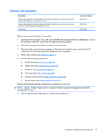
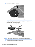
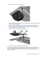
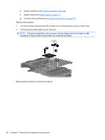
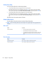
e. Display assembly (see Display assembly on page 68) f. System board (see System board on page 74) g. Fan/heat sink assembly (see Fan/heat sink assembly on page 77) Remove the processor: 1. Turn the processor locking screw (1) one-half turn counterclockwise until you hear a click. 2. Lift the processor (2) straight up and remove it. NOTE: The gold triangle (3) on the processor must be aligned with the triangle icon (4) embossed on the processor socket when you install the processor. Reverse this procedure to install the processor. 82 Chapter 4 Removal and replacement procedures
-
 1
1 -
2
-
3
-
4
-
5
-
6
-
7
-
8
-
9
-
10
-
11
-
12
-
13
-
14
-
15
-
16
-
17
-
18
-
19
-
20
-
21
-
22
-
23
-
24
-
25
-
26
-
27
-
28
-
29
-
30
-
31
-
32
-
33
-
34
-
35
-
36
-
37
-
38
-
39
-
40
-
41
-
42
-
43
-
44
-
45
-
46
-
47
-
48
-
49
-
50
-
51
-
52
-
53
-
54
-
55
-
56
-
57
-
58
-
59
-
60
-
61
-
62
-
63
-
64
-
65
-
66
-
67
-
68
-
69
-
70
-
71
-
72
-
73
-
74
-
75
-
76
-
77
-
78
-
79
-
80
-
81
-
82
-
83
-
84
-
85
-
86
-
 87
87 -
 88
88 -
 89
89 -
 90
90 -
 91
91 -
 92
92 -
 93
93 -
 94
94 -
 95
95 -
 96
96 -
 97
97 -
98
-
99
-
100
-
101
-
102
-
103
-
104
-
105
-
106
-
107
-
108
-
109
-
110
-
111
-
112
-
113
-
114
-
115
-
116
-
117
-
118
-
119
-
120
-
121
-
122
-
123
-
124
-
125
-
126
-
127
-
128
-
129
-
130
-
131
-
132
-
133
-
134
-
135
 |
 |
e.
Display assembly (see
Display assembly
on page
68
)
f.
System board (see
System board
on page
74
)
g.
Fan/heat sink assembly (see
Fan/heat sink assembly
on page
77
)
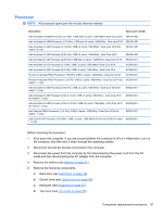
Remove the processor:
1.
Turn the processor locking screw
(1)
one-half turn counterclockwise until you hear a click.
2.
Lift the processor
(2)
straight up and remove it.
NOTE:
The gold triangle
(3)
on the processor must be aligned with the triangle icon
(4)
embossed on the processor socket when you install the processor.
Reverse this procedure to install the processor.
82
Chapter 4
Removal and replacement procedures