HP J4868A User Manual - Page 17
Installation Precautions:, Warning, Cautions - transceiver
 |
View all HP J4868A manuals
Add to My Manuals
Save this manual to your list of manuals |
Page 17 highlights
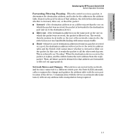
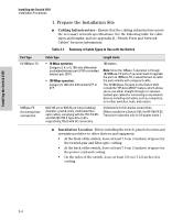
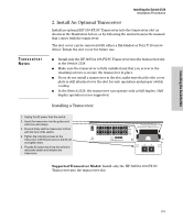
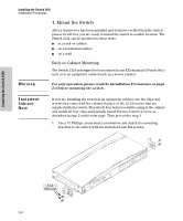
Installing the Switch 2124 Warning Cautions Installing the Switch 2124 Installation Procedures Installation Precautions: Follow these precautions when installing your HP Switch 2124. I The rack or cabinet should be adequately secured to prevent it from becoming unstable and/or falling over. Devices installed in a rack or cabinet should be mounted as low as possible, with the heaviest device at the bottom and progressively lighter devices installed above. I Make sure that the power source circuits are properly grounded, then use the power cord supplied with the switch to connect it to the power source. I If your installation requires a different power cord than the one supplied with the switch, be sure the cord is adequately sized for the switch's current requirements. In addition, be sure to use a power cord displaying the mark of the safety agency that defines the regulations for power cords in your country. The mark is your assurance that the power cord can be used safely with the switch. I When installing the switch, note that the AC outlet should be near the switch and should be easily accessible in case the switch must be powered off. I Ensure that the switch does not overload the power circuits, wiring, and over-current protection. To determine the possibility of overloading the supply circuits, add together the ampere ratings of all devices installed on the same circuit as the switch and compare the total with the rating limit for the circuit. The maximum ampere ratings are usually printed on the devices near the AC power connectors. I Do not install the switch in an environment where the operating ambient temperature might exceed 55C (131F). I Make sure the air flow around the sides and back of the switch is not restricted. I Make sure that if no transceiver is installed in the transceiver slot, the cover plate is installed to cover the slot. A cover plate is required for safe operation, and to ensure proper switch cooling. 2-3
-
 1
1 -
2
-
3
-
4
-
5
-
6
-
7
-
8
-
9
-
10
-
11
-
 12
12 -
 13
13 -
 14
14 -
 15
15 -
 16
16 -
 17
17 -
 18
18 -
 19
19 -
 20
20 -
 21
21 -
 22
22 -
23
-
24
-
25
-
26
-
27
-
28
-
29
-
30
-
31
-
32
-
33
-
34
-
35
-
36
-
37
-
38
-
39
-
40
-
41
-
42
-
43
-
44
-
45
-
46
-
47
-
48
-
49
-
50
-
51
-
52
-
53
-
54
-
55
-
56
-
57
-
58
-
59
-
60
 |
 |