HP J4868A User Manual - Page 20
Verify the Switch Operates Correctly
 |
View all HP J4868A manuals
Add to My Manuals
Save this manual to your list of manuals |
Page 20 highlights
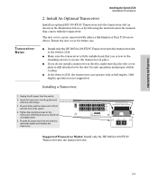
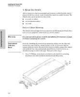
Installing the Switch 2124 Installing the Switch 2124 Installation Procedures 3. Verify the Switch Operates Correctly After you have optionally installed a transceiver, but before mounting the switch in its network location, you should first check that it is working properly by plugging it into a power source and verifying that it passes its self test. 1. Connect the power cord supplied with the switch to the power connector on the back of the switch, and then into a nearby properly grounded electrical outlet. Note Connect power cord to the power connector The Switch 2124 does not have a power switch. It is powered on when the power cord is connected to the switch and to a power source. For safety, the power outlet should be located near the switch installation. The switch automatically adjusts to any voltage between 100-240 volts and either 50 or 60 Hz. There are no voltage range settings required. If your switch requires a different power cord than the one supplied with the switch, please see the Installation Precautions on page 2-3. 2. Check the LEDs on the switch. The LED behavior is described on the next page. 2-6
-
 1
1 -
2
-
3
-
4
-
5
-
6
-
7
-
8
-
9
-
10
-
11
-
12
-
13
-
14
-
 15
15 -
 16
16 -
 17
17 -
 18
18 -
 19
19 -
 20
20 -
 21
21 -
 22
22 -
 23
23 -
 24
24 -
 25
25 -
26
-
27
-
28
-
29
-
30
-
31
-
32
-
33
-
34
-
35
-
36
-
37
-
38
-
39
-
40
-
41
-
42
-
43
-
44
-
45
-
46
-
47
-
48
-
49
-
50
-
51
-
52
-
53
-
54
-
55
-
56
-
57
-
58
-
59
-
60
 |
 |
