HP J4868A User Manual - Page 29
As a Segment Switch, Installing the Switch 2124, Switch 2124
 |
View all HP J4868A manuals
Add to My Manuals
Save this manual to your list of manuals |
Page 29 highlights
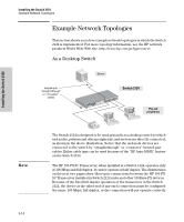
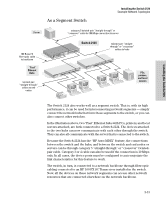
As a Segment Switch Installing the Switch 2124 Example Network Topologies Server category 5 twisted-pair "straight-through" or "crossover" cable for 100 Mbps connection to server 100 Base-FX fiber-optic cable to backbone "Fast" Ethernet Hubs twisted-pair "straight-through" cables to end nodes Switch 2124 twisted-pair "straightthrough" or "crossover" cables to hubs PCs, printers, and local servers Installing the Switch 2124 The Switch 2124 also works well as a segment switch. That is, with its high performance, it can be used for interconnecting network segments - simply connect the network hubs that form those segments to the switch, or you can also connect other switches. In the illustration above, two "Fast" Ethernet hubs with PCs, printers, and local servers attached, are both connected to a Switch 2124. The devices attached to the two hubs can now communicate with each other through the switch. They can also all communicate with the server that is connected to the switch. Because the Switch 2124 has the "HP Auto-MDIX" feature, the connections between the switch and the hubs, and between the switch and end nodes or servers can be through category 5 "straight-through" or "crossover" twistedpair cable. Category 3 or 4 cable can also be used if the connection is 10 Mbps only. In all cases, the device ports must be configured to auto negotiate the link characteristics for this feature to work. The switch, in turn, is connected to a network backbone through fiber-optic cabling connected to an HP 100-FX SC Transceiver installed in the switch. Now, all the devices on these network segments can access other network resources that are connected elsewhere on the network backbone. 2-15
-
 1
1 -
2
-
3
-
4
-
5
-
6
-
7
-
8
-
9
-
10
-
11
-
12
-
13
-
14
-
15
-
16
-
17
-
18
-
19
-
20
-
21
-
22
-
23
-
 24
24 -
 25
25 -
 26
26 -
 27
27 -
 28
28 -
 29
29 -
 30
30 -
 31
31 -
 32
32 -
 33
33 -
 34
34 -
35
-
36
-
37
-
38
-
39
-
40
-
41
-
42
-
43
-
44
-
45
-
46
-
47
-
48
-
49
-
50
-
51
-
52
-
53
-
54
-
55
-
56
-
57
-
58
-
59
-
60
 |
 |
