HP LH4r HP Netserver LH 3 Surestore E Installation Guide - Page 58
Disk Array Rear Panel, Disk Array Controls and Indicators cover open
 |
View all HP LH4r manuals
Add to My Manuals
Save this manual to your list of manuals |
Page 58 highlights
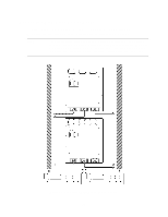
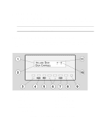
1 - Controller X SCSI Connector 1 4 - Controller Y SCSI Connector 2 2 - Controller X SCSI Connector 2 3 - Controller Y SCSI Connector 1 5 - P1-P3 AC Power Connectors Figure 2. Disk Array Rear Panel 1 - Power Module Status Light 5 - Control Panel Display 2 - Disk Module Status Light 3 - Fan Module Status Light 4 - Power/Standby Switch 6 - Control Panel Status Light 7 - Controller Module Status Light Figure 3. Disk Array Controls and Indicators (cover open) 8
-
 1
1 -
2
-
3
-
4
-
5
-
6
-
7
-
8
-
9
-
10
-
11
-
12
-
13
-
14
-
15
-
16
-
17
-
18
-
19
-
20
-
21
-
22
-
23
-
24
-
25
-
26
-
27
-
28
-
29
-
30
-
31
-
32
-
33
-
34
-
35
-
36
-
37
-
38
-
39
-
40
-
41
-
42
-
43
-
44
-
45
-
46
-
47
-
48
-
49
-
50
-
51
-
52
-
 53
53 -
 54
54 -
 55
55 -
 56
56 -
 57
57 -
 58
58 -
 59
59 -
 60
60 -
 61
61 -
 62
62 -
 63
63 -
64
-
65
-
66
-
67
-
68
-
69
-
70
 |
 |

8
1 – Controller X SCSI Connector 1
4 – Controller Y SCSI Connector 2
2 – Controller X SCSI Connector 2
5 – P1-P3 AC Power Connectors
3 – Controller Y SCSI Connector 1
Figure 2.
Disk Array Rear Panel
1 – Power Module Status Light
5 – Control Panel Display
2 – Disk Module Status Light
6 – Control Panel Status Light
3 – Fan Module Status Light
7 – Controller Module Status Light
4 – Power/Standby Switch
Figure 3. Disk Array Controls and Indicators (cover open)