HP Model 744 HP Model 744 Owner's Guide - Page 74
Model 744 Installation, Tools Required, Preliminary Requirements
 |
View all HP Model 744 manuals
Add to My Manuals
Save this manual to your list of manuals |
Page 74 highlights
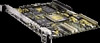
Typical Installation in a VME Card Cage Model 744 Installation Model 744 Installation Tools Required Model 744 installation requires the following tools: Tool Static grounding wrist strap (supplied with the installation kit) No. 1 Pozidriv screwdriver 5 mm (3/16 inch) nutdriver Light-duty flat-tipped screwdriver Used For Preventing static discharge problems Attaching accessory cards Attaching accessory cards Attaching accessory cards Preliminary Requirements Perform the following procedure before you install the board computer into the VME card cage: 1 Read the steps in "Configuring the VME Card Cage," earlier in this chapter. Installing a Single-Slot Model 744 into an HP Card Cage Follow these steps to install the Model 744 into the VME card cage: 1 Position the board computer at the desired slot and slide it into the card cage until it seats properly and the front panel is flush against the card cage. 2 Push both ejector levers in until they are flush with the front panel. 3 Engage and tighten the captive screws (labeled 1 and 2 in Figure 3-2) at each end of the board computer. These screws hold the computer in the VME card cage. 3-8
-
 1
1 -
2
-
3
-
4
-
5
-
6
-
7
-
8
-
9
-
10
-
11
-
12
-
13
-
14
-
15
-
16
-
17
-
18
-
19
-
20
-
21
-
22
-
23
-
24
-
25
-
26
-
27
-
28
-
29
-
30
-
31
-
32
-
33
-
34
-
35
-
36
-
37
-
38
-
39
-
40
-
41
-
42
-
43
-
44
-
45
-
46
-
47
-
48
-
49
-
50
-
51
-
52
-
53
-
54
-
55
-
56
-
57
-
58
-
59
-
60
-
61
-
62
-
63
-
64
-
65
-
66
-
67
-
68
-
 69
69 -
 70
70 -
 71
71 -
 72
72 -
 73
73 -
 74
74 -
 75
75 -
 76
76 -
 77
77 -
 78
78 -
 79
79 -
80
-
81
-
82
-
83
-
84
-
85
-
86
-
87
-
88
-
89
-
90
-
91
-
92
-
93
-
94
-
95
-
96
-
97
-
98
-
99
-
100
-
101
-
102
-
103
-
104
-
105
-
106
-
107
-
108
-
109
-
110
-
111
-
112
-
113
-
114
-
115
-
116
-
117
-
118
-
119
-
120
-
121
-
122
-
123
-
124
-
125
-
126
-
127
-
128
-
129
-
130
-
131
-
132
-
133
-
134
-
135
-
136
-
137
-
138
-
139
-
140
-
141
-
142
-
143
-
144
-
145
-
146
-
147
-
148
-
149
-
150
-
151
-
152
-
153
-
154
 |
 |
