HP P6000 HP P6300/P6500 EVA M6612/6625 Disk Enclosure Installation Instruction - Page 10
Cabling the P6300 EVA enclosure while online, Open HP P6000 Command View. - power supply upgrade
 |
View all HP P6000 manuals
Add to My Manuals
Save this manual to your list of manuals |
Page 10 highlights
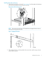
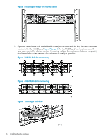
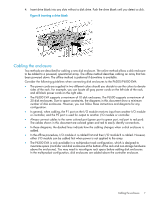
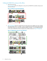
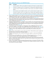
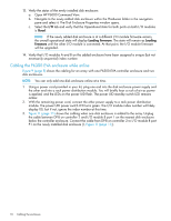
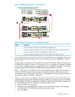
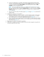
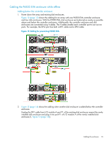
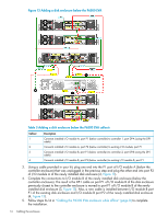
13. Verify the status of the newly installed disk enclosure: a. Open HP P6000 Command View. b. Navigate to the newly added disk enclosure within the Hardware folder in the navigation pane and select it. The Disk Enclosure Properties window opens. c. Select the I/O tab and verify that the Operational state for both ports on both I/O modules is Good. NOTE: If the newly added disk enclosure is at a different I/O module firmware version, the overall operational state will display Loading firmware. The state will remain as Loading firmware until the other I/O module is connected. At that point, the I/O module firmware will be upgraded. 14. Verify that I/O modules A and B on the added enclosure have been assigned a unique (but not necessarily sequential) index number. Cabling the P6300 EVA enclosure while online Figure 9 (page 8) shows the cabling for an array with one P6300 EVA controller enclosure and two disk enclosures. NOTE: You can only add one disk enclosure online at a time. 1. Using a power cord provided in your kit, plug one end into the disk enclosure power supply and the other end into a rack power distribution module. You will briefly hear a rush of air as power is applied, and the LEDs on the power UID flash. The power UID standby switch LED remains amber. 2. With the remaining power cord, connect the other power supply to a rack power distribution module. The power UID power switch LED turns green. The I/O module index number will likely display 00, but if not, ignore the index number at this time. 3. Figure 11 (page 11) shows the cabling when one disk enclosure is added to the array. Unplug the cable between DP-B on controller 2 and I/O module B port 1 on the nearest disk enclosure below the controller enclosure. Connect the cable from DP-B on controller 2 to I/O module B port P1 on the newly installed disk enclosure (1, Figure 11 (page 11)). 10 Cabling the enclosure
-
 1
1 -
2
-
3
-
4
-
 5
5 -
 6
6 -
 7
7 -
 8
8 -
 9
9 -
 10
10 -
 11
11 -
 12
12 -
 13
13 -
 14
14 -
 15
15 -
16
-
17
 |
 |