HP P6000 HP P6300/P6500 EVA M6612/6625 Disk Enclosure Installation Instruction - Page 7
Cabling the enclosure
 |
View all HP P6000 manuals
Add to My Manuals
Save this manual to your list of manuals |
Page 7 highlights
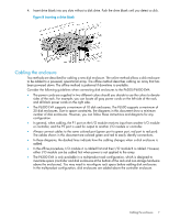
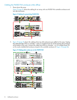
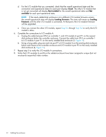
4. Insert drive blank into any slots without a disk drive. Push the drive blank until you detect a click. Figure 8 Inserting a drive blank Cabling the enclosure Two methods are described for cabling a new disk enclosure. The online method allows a disk enclosure to be added to a powered, operational array. The offline method describes cabling an array that has been powered down. The offline method is preferred if downtime is available. Consider the following guidelines when connecting disk enclosures to the P6300/P6500 EVA: • The power cords are supplied in two different colors should you decide to use the colors to denote sides of the rack. For example, you can locate all gray power cords on the left side of the rack, and all black power cords on the right side. • The P6300 EVA supports a maximum of 10 disk enclosures. The P6500 supports a maximum of 20 disk enclosures. Due to space constraints, the diagrams in this document show a minimum number of disk enclosures. However, you can follow these instructions and diagrams for any configuration. • In general, when cabling, the P1 port on the I/O module receives input from another I/O module or controller, and the P2 port is used for output to another I/O module or controller. • Always connect cables to the same colored port (green port to green port, red port to red port). The cables shown in this document are colored green and red to easily identify connections. • In these diagrams, the dashed lines indicate how the cabling changes when a disk enclosure is added. • In the offline procedure, I/O module A is cabled first and then I/O module B is cabled. However, either I/O module can be cabled first when power is not applied to the array. • The P6300 EVA is only available in a multiproduct rack configuration, which is designed to maximize space (controller and disk enclosures at the bottom of the rack and non-storage hardware above the enclosures). You may need to reconfigure rack space before adding disk enclosures. In the multiproduct configuration, disk enclosures are added above the controller enclosure. Cabling the enclosure 7
-
 1
1 -
 2
2 -
 3
3 -
 4
4 -
 5
5 -
 6
6 -
 7
7 -
 8
8 -
 9
9 -
 10
10 -
 11
11 -
 12
12 -
13
-
14
-
15
-
16
-
17
 |
 |
