HP P6000 HP P6300/P6500 EVA M6612/6625 Disk Enclosure Installation Instruction - Page 16
Cabling the P6500 EVA enclosure while online
 |
View all HP P6000 manuals
Add to My Manuals
Save this manual to your list of manuals |
Page 16 highlights
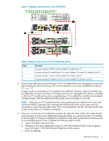
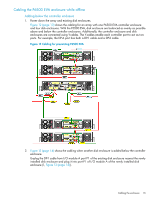
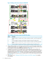
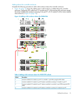
2. Using a cable provided in your kit, plug one end into the P1 port of I/O module A (above the controller enclosure) that was unplugged in the previous step and plug the other end into port P2 of I/O module A of the newly installed disk enclosure (2, Figure 14). 3. Complete the connections to I/O module B of the newly installed disk enclosure (above the controller enclosure). The result is the DP-2 cable on port P1 of I/O module B of the disk enclosure previously at the top is moved to port P1 of I/O module B of the newly installed disk enclosure (3, Figure 14). Also, a new cable is installed between I/O module B P1 of the existing disk enclosure and I/O module B port P2 of the newly installed disk enclosure (4, Figure 14). 4. Follow steps 8-14 in "Cabling the P6300 EVA enclosure while offline" (page 8) to complete the installation. Cabling the P6500 EVA enclosure while online Figure 12 (page 13) shows the cabling for an array with one P6500 EVA controller enclosure and four disk enclosures. With the P6500 EVA, disk enclosure are balanced as evenly as possible above and below the controller enclosure. Additionally, the controller enclosure and disk enclosures are connected using Y-cables. The Y-cables enable each controller port to act as two ports. For example, the DP-A port has both a DP-1 cable and a DP-2 cable. Figure 13 (page 14) shows the cabling when another disk enclosure is added to the array below the controller enclosure. Figure 14 (page 15) shows the cabling when a disk enclosure is added to the array above the controller enclosure. The remaining steps in this procedure apply when the disk enclosure is added below the controller enclosure. However, you can adapt these steps for the addition above the controller enclosure. Once you place the new disk enclosures in the rack, complete the following procedure to add each new disk enclosure online. NOTE: You can only add one disk enclosure online at a time. 1. Using a power cord provided in your kit, plug one end into the disk enclosure power supply and the other end into a rack power distribution module. You will briefly hear a rush of air as power is applied, and the LEDs on the power UID flash. The power UID standby switch LED remains amber. 2. With the remaining power cord, connect the other power supply to a rack power distribution module. The power UID power switch LED turns green. The I/O module index number will likely display 00, but if not, ignore the index number at this time. 3. Unplug the DP-1 cable from I/O module A port P1 of the existing disk enclosure nearest the newly installed disk enclosure and plug it into port P1 of I/O module A of the newly installed disk enclosure (1, Figure 13 (page 14)). 4. Using a cable provided in your kit, plug one end into the P1 port of I/O module A (below the controller enclosure) that was unplugged in the previous step and plug the other end into port P2 of I/O module A of the newly installed disk enclosure (2, Figure 13). Note the enclosure ID shown on the I/O module to determine which one to observe with HP P6000 Command View. In this step, connections to I/O module A are made first. However, either I/O module can be cabled first as long as the other I/O module ports are not unplugged until cabling is complete on the first I/O module and you have completed step 5. This enables the controllers to redundantly manage storage while the cables are briefly pulled and reconnected on one side. NOTE: With only one I/O module from the newly added enclosure cabled to the array, there will be HP P6000 Command View warnings that indicate disk drives in the system are only connected on one of the redundant Fibre Channel loops. This is to be expected, and the warnings should clear as soon as the other I/O module is connected. 5. Once you connect one I/O module (for example, A), verify the status of the I/O module A ports and the presence of the newly added disk enclosure (using the enclosure ID noted in the previous step) before you connect the other I/O module (in this example, B). Failure to complete this 16 Cabling the enclosure
-
 1
1 -
2
-
3
-
4
-
5
-
6
-
7
-
8
-
9
-
10
-
 11
11 -
 12
12 -
 13
13 -
 14
14 -
 15
15 -
 16
16 -
 17
17
 |
 |