HP P6000 HP P6300/P6500 EVA M6612/6625 Disk Enclosure Installation Instruction - Page 14
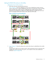
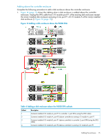
Adding a disk enclosure below the P6500 EVA
 |
View all HP P6000 manuals
Add to My Manuals
Save this manual to your list of manuals |
Page 14 highlights
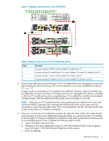
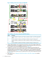
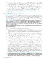
Figure 13 Adding a disk enclosure below the P6500 EVA Table 3 Adding a disk enclosure below the P6500 EVA callouts Callout 1 2 3 4 Description Connects installed I/O module A, port P1 (below controller) to controller 1, port DP-A (using the DP-1 cable) Connects installed I/O module A, port P2 (below controller) to existing I/O module, port P1 Connects installed I/O module B, port P1 (below controller) to controller 2, port DP-B (using the DP-1 cable) Connects installed I/O module B, port P2 (below controller) to existing I/O module B, port P1 3. Using a cable provided in your kit, plug one end into the P1 port of I/O module A (below the controller enclosure) that was unplugged in the previous step and plug the other end into port P2 of I/O module A of the newly installed disk enclosure (2, Figure 13). 4. Complete the connections to I/O module B of the newly installed disk enclosure (below the controller enclosure). The result is the DP-1 cable on port P1 of I/O module B of the disk enclosure previously closest to the controller enclosure is moved to port P1 of I/O module B of the newly installed disk enclosure (3, Figure 13). Also, a new cable is installed between I/O module B port P1 of the existing disk enclosure and I/O module B port P2 of the newly installed disk enclosure (4, Figure 13). 5. Follow steps 8-14 in "Cabling the P6300 EVA enclosure while offline" (page 8) to complete the installation. 14 Cabling the enclosure
-
 1
1 -
2
-
3
-
4
-
5
-
6
-
7
-
8
-
 9
9 -
 10
10 -
 11
11 -
 12
12 -
 13
13 -
 14
14 -
 15
15 -
 16
16 -
 17
17
 |
 |
