HP P6000 HP P6300/P6500 EVA M6612/6625 Disk Enclosure Installation Instruction - Page 9
Table 1 Adding disk enclosures to the P6300 EVA callouts - power supply
 |
View all HP P6000 manuals
Add to My Manuals
Save this manual to your list of manuals |
Page 9 highlights
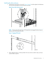
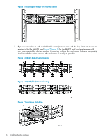
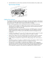
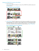
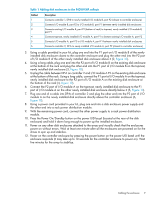
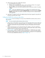
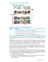
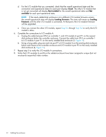
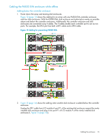
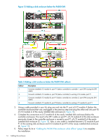
Table 1 Adding disk enclosures to the P6300 EVA callouts Callout 1 2 3 4 5 6 Description Connects controller 1, DP-B to newly installed I/O module B, port P2 (closest to controller enclosure) Connects I/O module B, port P2 to I/O module B, port P1 between newly installed disk enclosures Connects existing I/O module B, port P2 (bottom of rack) to topmost, newly installed I/O module B, port P1 Connects topmost, newly installed I/O module A, port P1 to bottom existing I/O module A, port P2 Connects I/O module A, port P2 to I/O module A, port P1 between newly installed disk enclosures Connects controller 2, DP-A to newly installed I/O module A, port P2 (closest to controller enclosure) 3. Using a cable provided in your kit, plug one end into the P1 port on I/O module B of the newly installed disk enclosure closest to the controller enclosure and plug the other end into the P2 port of I/O module B of the other newly installed disk enclosure above it (2, Figure 10). 4. Using a long cable, plug one end into the P2 port of I/O module B on the existing disk enclosure at the bottom of the rack and plug the other end into the P1 port of I/O module B on the topmost, newly installed disk enclosure (3, Figure 10). 5. Unplug the cable between DP-A on controller 2 and I/O module A P2 on the existing disk enclosure at the bottom of the rack. Using a long cable, connect the P1 port of I/O module A on the topmost, newly installed disk enclosure to the P2 port of I/O module A on the existing disk enclosure at the bottom of the rack (4, Figure 10). 6. Connect the P2 port of I/O module A on the topmost, newly installed disk enclosure to the P1 port of I/O module A on the other newly installed disk enclosure directly below it (5, Figure 10). 7. Plug one end of a cable into DP-A of controller 2 and plug the other end into the P2 port of I/O module A on the newly installed disk enclosure directly above the controller enclosure (6, Figure 10). 8. Using a power cord provided in your kit, plug one end into a disk enclosure power supply and the other end into a rack power distribution module. 9. With the remaining power cord, connect the other power supply to a rack power distribution module. 10. Press the Power On/Standby button on the power UID bezel (located at the rear of the disk enclosure) and hold it down long enough to power up the installed enclosure. 11. Power on any other disk enclosures attached to the array and visually check that the enclosures power on without errors. Wait at least one minute after all the enclosures are powered on for the drives to spin up and stabilize. 12. Power on the controller enclosure by pressing the power button on the power UID bezel until the enclosure responds (it may take up to 10 seconds for the controller enclosure to power on). Wait five minutes for the array to stabilize. Cabling the enclosure 9
-
 1
1 -
2
-
3
-
 4
4 -
 5
5 -
 6
6 -
 7
7 -
 8
8 -
 9
9 -
 10
10 -
 11
11 -
 12
12 -
 13
13 -
 14
14 -
15
-
16
-
17
 |
 |
