HP P6000 HP P6300/P6500 EVA M6612/6625 Disk Enclosure Installation Instruction - Page 12
Step 5.b, - firmware
 |
View all HP P6000 manuals
Add to My Manuals
Save this manual to your list of manuals |
Page 12 highlights
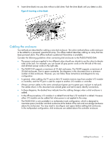
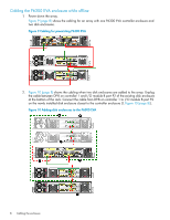
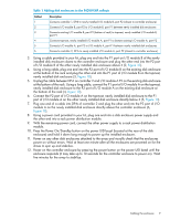
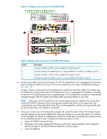
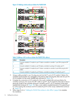
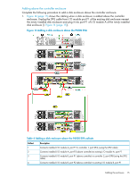
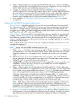
d. For the I/O module that you connected, check that the overall operational state and the connection and operational states for each port displays Good. The other I/O module that is not yet connected will display Not installed for the overall operational state and Not available for each port operational state. NOTE: If the newly added disk enclosure is at a different I/O module firmware version, the overall operational state will display Loading firmware. The state will remain as Loading firmware until the other I/O module is connected. At that point, the I/O module firmware will be upgraded. e. Once you connect the other I/O module, repeat Step 5.b through Step 5.d to verify that I/O module's status. 6. Complete the connections to I/O module A: a. Unplug the cable between DP-A on controller 1 and I/O module A port P1 on the nearest disk enclosure below the controller enclosure. Connect the cable from DP-A on controller 1 to I/O module A port P1 on the newly installed disk enclosure (3, Figure 11). b. Using a long cable, plug one end into port P1 of I/O module A on the existing disk enclosure below and closest to the controller enclosure and I/O module A port P2 on the newly installed disk enclosure (4, Figure 11). 7. Repeat step 5 to verify the I/O module A connections. 8. Verify that I/O modules A and B on the added enclosure have been assigned a unique (but not necessarily sequential) index number. 12 Cabling the enclosure
-
 1
1 -
2
-
3
-
4
-
5
-
6
-
 7
7 -
 8
8 -
 9
9 -
 10
10 -
 11
11 -
 12
12 -
 13
13 -
 14
14 -
 15
15 -
 16
16 -
 17
17
 |
 |
