HP Pavilion 14-n100 Maintenance and Service Guide - Page 102
spare part kits., Thermal paste is used on the processor
 |
View all HP Pavilion 14-n100 manuals
Add to My Manuals
Save this manual to your list of manuals |
Page 102 highlights
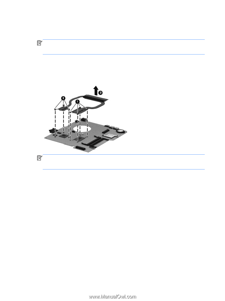
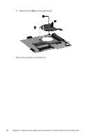
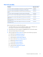
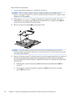
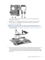
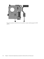
Remove the heat sink assembly: 1. Turn the system board upside down, with the front toward you. NOTE: Steps 2 through 4 apply to computer models equipped with switchable discrete graphics. See steps 5 through 7 for heat sink assembly removal information for computer models equipped with UMA graphics. 2. Following the 1, 2, 3, 4, 5, 6, 7 sequence stamped into the heat sink assembly, loosen the 4 Phillips PM2.0×10.0 captive screws (1) and the 3 Phillips PM2.0×3.5 captive screws (2) that secure the heat sink assembly to the system board. 3. Remove the heat sink assembly (3) from the system board. NOTE: Due to the adhesive quality of the thermal material located between the heat sink assembly and the system board components, it may be necessary to move the heat sink assembly from side to side to detach it. 4. Remove the thermal material. The thermal material must be thoroughly cleaned from the surfaces of the heat sink assembly and the system board components each time the heat sink assembly is removed. Replacement thermal material is included with the heat sink assembly and system board spare part kits. ● Thermal paste is used on the processor (1) and the heat sink assembly section (2) that services it ● Thermal paste is used on the graphics subsystem chip (3) and the heat sink assembly section (4) that services it 92 Chapter 6 Removal and replacement procedures for Authorized Service Provider parts
-
 1
1 -
2
-
3
-
4
-
5
-
6
-
7
-
8
-
9
-
10
-
11
-
12
-
13
-
14
-
15
-
16
-
17
-
18
-
19
-
20
-
21
-
22
-
23
-
24
-
25
-
26
-
27
-
28
-
29
-
30
-
31
-
32
-
33
-
34
-
35
-
36
-
37
-
38
-
39
-
40
-
41
-
42
-
43
-
44
-
45
-
46
-
47
-
48
-
49
-
50
-
51
-
52
-
53
-
54
-
55
-
56
-
57
-
58
-
59
-
60
-
61
-
62
-
63
-
64
-
65
-
66
-
67
-
68
-
69
-
70
-
71
-
72
-
73
-
74
-
75
-
76
-
77
-
78
-
79
-
80
-
81
-
82
-
83
-
84
-
85
-
86
-
87
-
88
-
89
-
90
-
91
-
92
-
93
-
94
-
95
-
96
-
 97
97 -
 98
98 -
 99
99 -
 100
100 -
 101
101 -
 102
102 -
 103
103 -
 104
104 -
 105
105 -
 106
106 -
 107
107 -
108
-
109
-
110
-
111
-
112
-
113
-
114
-
115
-
116
-
117
-
118
-
119
-
120
-
121
-
122
-
123
-
124
-
125
-
126
-
127
-
128
-
129
-
130
-
131
-
132
-
133
-
134
-
135
-
136
-
137
-
138
-
139
-
140
-
141
-
142
 |
 |