HP Pavilion 15-ck000 Maintenance and Service Guide - Page 73
that secure the webcam/microphone module cable to the display back
 |
View all HP Pavilion 15-ck000 manuals
Add to My Manuals
Save this manual to your list of manuals |
Page 73 highlights
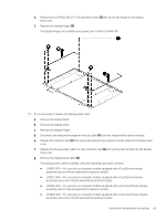
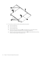
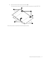
e. Remove the six Phillips M2.5×3.1 broad head screws (2) that secure the hinges to the display back cover. f. Remove the display hinges (3). The display hinges are available using spare part number L01844-001. 11. If it is necessary to replace the display panel cable: a. Remove the display bezel. b. Remove the display panel. c. Remove the display hinges. d. Disconnect the webcam/microphone module cable (1) from the webcam/microphone module. e. Release the retention tabs (2) that secure the webcam/microphone module cable to the display back cover. f. Release the display panel cable from the retention clips (3) and routing channel built into the display back cover. g. Remove the display panel cable (4). The display panel cable is available using the following spare part numbers: ● L04970-001 - For use only on computer models equipped with a TouchScreen display assembly and an infrared webcam/microphone module ● L04972-001 - For use only on computer models equipped with a TouchScreen display assembly and a non-infrared webcam/microphone module ● L02663-001 - For use only on computer models equipped with a non-TouchScreen display assembly and an infrared webcam/microphone module ● L01858-001 - For use only on computer models equipped with a non-TouchScreen display assembly and a non-infrared webcam/microphone module Component replacement procedures 65
-
 1
1 -
2
-
3
-
4
-
5
-
6
-
7
-
8
-
9
-
10
-
11
-
12
-
13
-
14
-
15
-
16
-
17
-
18
-
19
-
20
-
21
-
22
-
23
-
24
-
25
-
26
-
27
-
28
-
29
-
30
-
31
-
32
-
33
-
34
-
35
-
36
-
37
-
38
-
39
-
40
-
41
-
42
-
43
-
44
-
45
-
46
-
47
-
48
-
49
-
50
-
51
-
52
-
53
-
54
-
55
-
56
-
57
-
58
-
59
-
60
-
61
-
62
-
63
-
64
-
65
-
66
-
67
-
 68
68 -
 69
69 -
 70
70 -
 71
71 -
 72
72 -
 73
73 -
 74
74 -
 75
75 -
 76
76 -
 77
77 -
 78
78 -
79
-
80
-
81
-
82
-
83
-
84
-
85
-
86
-
87
-
88
-
89
-
90
-
91
 |
 |
