HP Pavilion 17-ar000 Maintenance and Service Guide - Page 46
from the keyboard/top cover. The connector board cable is, Detach the connector board cable
 |
View all HP Pavilion 17-ar000 manuals
Add to My Manuals
Save this manual to your list of manuals |
Page 46 highlights
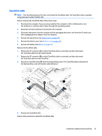
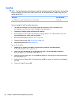
NOTE: The #1/white wireless antenna cable connects to the WLAN module "#1/Main" terminal. The #2/ black wireless antenna cable connects to the WLAN module "#2/Aux" terminal. (4) Power connector cable (5) Display panel ZIF connector cable (6) Speaker cable (7) TouchPad ZIF connector cable (8) Keyboard ZIF connector cable 2. Detach the connector board cable (9) from the keyboard/top cover. (The connector board cable is attached to the keyboard/top cover with double-sided adhesive.) 3. Remove the nine Phillips PM2.0×4.2 screws (1) that secure the system board to the keyboard/top cover. 38 Chapter 5 Removal and replacement procedures
-
 1
1 -
2
-
3
-
4
-
5
-
6
-
7
-
8
-
9
-
10
-
11
-
12
-
13
-
14
-
15
-
16
-
17
-
18
-
19
-
20
-
21
-
22
-
23
-
24
-
25
-
26
-
27
-
28
-
29
-
30
-
31
-
32
-
33
-
34
-
35
-
36
-
37
-
38
-
39
-
40
-
 41
41 -
 42
42 -
 43
43 -
 44
44 -
 45
45 -
 46
46 -
 47
47 -
 48
48 -
 49
49 -
 50
50 -
 51
51 -
52
-
53
-
54
-
55
-
56
-
57
-
58
-
59
-
60
-
61
-
62
-
63
-
64
-
65
-
66
-
67
-
68
-
69
-
70
-
71
-
72
-
73
-
74
-
75
-
76
-
77
-
78
-
79
-
80
-
81
-
82
-
83
 |
 |

NOTE:
The #1/white wireless antenna cable connects to the WLAN module "#1/Main" terminal. The
#2/ black wireless antenna cable connects to the WLAN module "#2/Aux" terminal.
(4)
Power connector cable
(5)
Display panel ZIF connector cable
(6)
Speaker cable
(7)
TouchPad ZIF connector cable
(8)
Keyboard ZIF connector cable
2.
Detach the connector board cable
(9)
from the keyboard/top cover. (The connector board cable is
attached to the keyboard/top cover with double-sided adhesive.)
3.
Remove the nine Phillips PM2.0×4.2 screws
(1)
that secure the system board to the keyboard/top cover.
38
Chapter 5
Removal and replacement procedures