HP Pavilion Touch 14-n200 Maintenance and Service Guide 1 - Page 62
Display panel, and the two Phillips M2.5×3.0 screws
 |
View all HP Pavilion Touch 14-n200 manuals
Add to My Manuals
Save this manual to your list of manuals |
Page 62 highlights
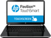
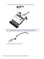
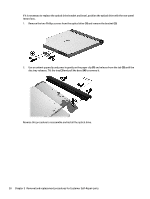
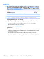
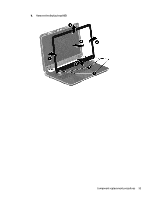
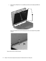
Display panel NOTE: These procedures are for replacing the display panel for HP Pavilion Notebook. For procedures to replace the HP Pavilion Notebook display assembly subcomponents, see Display assembly on page 88 and then Display assembly subcomponents on page 90. For procedures to replace the HP Pavilion TouchSmart display assembly, see Display assembly on page 88. Description Display bezel (includes screws) Display panel, 14 in (35.56 cm), WLED, HD, BrightView flat display panel Spare part number 739355-001 734420-001 IMPORTANT: Make special note of each screw and screw lock size and location during removal and replacement Before removing the display panel, follow these steps: 1. Turn off the computer. If you are unsure whether the computer is off or in Hibernation, turn the computer on, and then shut it down through the operating system. 2. Disconnect the power from the computer by unplugging the power cord from the computer. 3. Disconnect all external devices from the computer. 4. Remove the battery (see Battery on page 42). Remove the panel: If it is necessary to replace the display bezel: 1. Remove the plastic screw covers (1) and the two Phillips M2.5×3.0 screws (2) that secure the display bezel to the display assembly. 2. If it is necessary to replace the display bezel or any of the display assembly subcomponents: a. Flex the inside edges of the bottom edge (3), the left and right sides (4), and the top edge (5) of the display bezel until the bezel disengages from the display enclosure. 52 Chapter 6 Removal and replacement procedures for Authorized Service Provider parts
-
 1
1 -
2
-
3
-
4
-
5
-
6
-
7
-
8
-
9
-
10
-
11
-
12
-
13
-
14
-
15
-
16
-
17
-
18
-
19
-
20
-
21
-
22
-
23
-
24
-
25
-
26
-
27
-
28
-
29
-
30
-
31
-
32
-
33
-
34
-
35
-
36
-
37
-
38
-
39
-
40
-
41
-
42
-
43
-
44
-
45
-
46
-
47
-
48
-
49
-
50
-
51
-
52
-
53
-
54
-
55
-
56
-
 57
57 -
 58
58 -
 59
59 -
 60
60 -
 61
61 -
 62
62 -
 63
63 -
 64
64 -
 65
65 -
 66
66 -
 67
67 -
68
-
69
-
70
-
71
-
72
-
73
-
74
-
75
-
76
-
77
-
78
-
79
-
80
-
81
-
82
-
83
-
84
-
85
-
86
-
87
-
88
-
89
-
90
-
91
-
92
-
93
-
94
-
95
-
96
-
97
-
98
-
99
-
100
-
101
-
102
-
103
-
104
-
105
-
106
-
107
-
108
-
109
-
110
-
111
-
112
-
113
-
114
-
115
-
116
-
117
-
118
-
119
-
120
-
121
-
122
-
123
-
124
-
125
-
126
-
127
-
128
-
129
 |
 |