HP Pavilion Touch 14-n200 Maintenance and Service Guide 1 - Page 80
Reverse this procedure to install the optical drive connector cable., built into the base enclosure.
 |
View all HP Pavilion Touch 14-n200 manuals
Add to My Manuals
Save this manual to your list of manuals |
Page 80 highlights
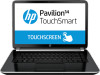
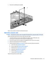
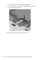
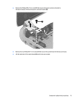
1. Disconnect the optical drive connector cable (1) from the system board. 2. Release the optical drive connector cable from the clip (2) built into the base enclosure. 3. Remove the optical drive connector cable. Reverse this procedure to install the optical drive connector cable. 70 Chapter 6 Removal and replacement procedures for Authorized Service Provider parts
-
 1
1 -
2
-
3
-
4
-
5
-
6
-
7
-
8
-
9
-
10
-
11
-
12
-
13
-
14
-
15
-
16
-
17
-
18
-
19
-
20
-
21
-
22
-
23
-
24
-
25
-
26
-
27
-
28
-
29
-
30
-
31
-
32
-
33
-
34
-
35
-
36
-
37
-
38
-
39
-
40
-
41
-
42
-
43
-
44
-
45
-
46
-
47
-
48
-
49
-
50
-
51
-
52
-
53
-
54
-
55
-
56
-
57
-
58
-
59
-
60
-
61
-
62
-
63
-
64
-
65
-
66
-
67
-
68
-
69
-
70
-
71
-
72
-
73
-
74
-
 75
75 -
 76
76 -
 77
77 -
 78
78 -
 79
79 -
 80
80 -
 81
81 -
 82
82 -
 83
83 -
 84
84 -
 85
85 -
86
-
87
-
88
-
89
-
90
-
91
-
92
-
93
-
94
-
95
-
96
-
97
-
98
-
99
-
100
-
101
-
102
-
103
-
104
-
105
-
106
-
107
-
108
-
109
-
110
-
111
-
112
-
113
-
114
-
115
-
116
-
117
-
118
-
119
-
120
-
121
-
122
-
123
-
124
-
125
-
126
-
127
-
128
-
129
 |
 |
1.
Disconnect the optical drive connector cable
(1)
from the system board.
2.
Release the optical drive connector cable from the clip
(2)
built into the base enclosure.
3.
Remove the optical drive connector cable.
Reverse this procedure to install the optical drive connector cable.
70
Chapter 6
Removal and replacement procedures for Authorized Service Provider parts