HP Pavilion dm1-2000 HP Pavilion dm1 Notebook PC - Maintenance and Service Gui - Page 74
System board, Hard drive see
 |
View all HP Pavilion dm1-2000 manuals
Add to My Manuals
Save this manual to your list of manuals |
Page 74 highlights
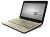
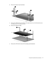
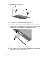
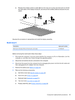
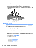
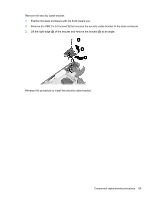
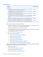
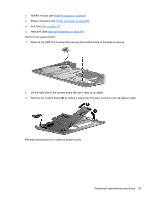
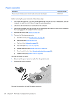
System board Description Spare part number System board: ● With AMD Athlon II Neo K125 1.7-GHz single core processor, 1-MB Level 2 cache, 800-MHz 608640-001 FSB, 1024-MB base memory, and replacement thermal material ● With AMD Athlon II Neo K325 1.3-GHz dual core processor, 2-MB Level 2 cache, 800-MHz FSB, 608641-001 1024-MB base memory, and replacement thermal material ● With AMD Turion II Neo K625 1.5-GHz dual core processor, 2-MB Level 2 cache, 800-MHz FSB, 608642-001 1024-MB base memory, and replacement thermal material ● With onboard AMD Athlon II Neo K125 1.7-GHz single core processor, for use with WWAN SKUs 616522-001 only, 1-MB Level 2 cache, 800-MHz FSB, 1024-MB base memory, and replacement thermal material ● With AMD Athlon II Neo K325 1.3-GHz dual core processor, for use with WWAN SKUs only, 2- 616523-001 MB Level 2 cache, 800-MHz FSB, 1024-MB base memory, and replacement thermal material ● With AMD Turion II Neo K625 1.5-GHz dual core processor, for use with WWAN SKUs only, 2- 616524-001 MB Level 2 cache, 800-MHz FSB, 1024-MB base memory, and replacement thermal material Before removing the system board, follow these steps: 1. Shut down the computer. If you are unsure whether the computer is off or in Hibernation, turn the computer on, and then shut it down through the operating system. 2. Disconnect all external devices connected to the computer. 3. Disconnect the power from the computer by first unplugging the power cord from the AC outlet and then unplugging the AC adapter from the computer. 4. Remove the battery (see Battery on page 36). 5. Remove the following components: a. hard drive cover (see WLAN module on page 38). b. Hard drive (see Drives on page 44). c. Keyboard (see Keyboard on page 47). d. Top cover (see Top cover on page 50). e. Display assembly (see Display assembly on page 58). f. Security cable bracket (see Security cable bracket on page 64). When replacing the system board, be sure that the following components are removed from the defective system board and installed on the replacement system board: ● SIM (see SIM on page 37) ● WLAN module (see WLAN module on page 38). ● RTC battery (see RTC battery on page 42). ● Memory module (see Memory module on page 43). 66 Chapter 4 Removal and replacement procedures
-
 1
1 -
2
-
3
-
4
-
5
-
6
-
7
-
8
-
9
-
10
-
11
-
12
-
13
-
14
-
15
-
16
-
17
-
18
-
19
-
20
-
21
-
22
-
23
-
24
-
25
-
26
-
27
-
28
-
29
-
30
-
31
-
32
-
33
-
34
-
35
-
36
-
37
-
38
-
39
-
40
-
41
-
42
-
43
-
44
-
45
-
46
-
47
-
48
-
49
-
50
-
51
-
52
-
53
-
54
-
55
-
56
-
57
-
58
-
59
-
60
-
61
-
62
-
63
-
64
-
65
-
66
-
67
-
68
-
 69
69 -
 70
70 -
 71
71 -
 72
72 -
 73
73 -
 74
74 -
 75
75 -
 76
76 -
 77
77 -
 78
78 -
 79
79 -
80
-
81
-
82
-
83
-
84
-
85
-
86
-
87
-
88
-
89
-
90
-
91
-
92
-
93
-
94
-
95
-
96
-
97
-
98
-
99
-
100
-
101
-
102
-
103
-
104
-
105
-
106
-
107
-
108
-
109
-
110
-
111
 |
 |