HP Pavilion dm3-1000 HP Pavilion dm3 Entertainment PC - Maintenance and Servic - Page 59
If it is necessary to replace the display bezel or any of the display assembly internal components
 |
View all HP Pavilion dm3-1000 manuals
Add to My Manuals
Save this manual to your list of manuals |
Page 59 highlights
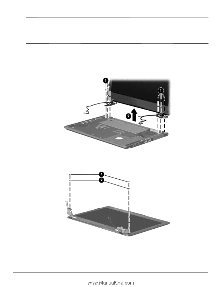
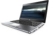
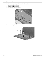
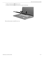
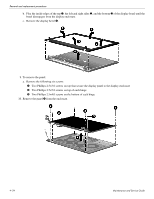
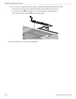
Removal and replacement procedures Ä CAUTION: Support the display assembly when removing the following screws. Failure to support the display assembly can result in damage to the display assembly and other computer components. 7. Release the hinges by removing the six Phillips PM2.5x5.0 screws 1 that secure it to the base enclosure. First remove the left hinge and then the right. ✎ On the left side, one of the screws secures a display support strap. On the right side, the left-most screw secures a ground strap for the wireless cables. After removing all six screws, note that the power cable on the left hinge may interfere with the removal of the display. Simply move the panel around the cable and then lift. On the right side, there is a metal plate that you must workaround to remove the display. 8. If it is necessary to replace the display bezel or any of the display assembly internal components: a. Remove the two rubber screw covers 1 and the two Phillips 2.0×5.0 screws 2 that secure the display bezel to the display assembly. Maintenance and Service Guide 4-23
-
 1
1 -
2
-
3
-
4
-
5
-
6
-
7
-
8
-
9
-
10
-
11
-
12
-
13
-
14
-
15
-
16
-
17
-
18
-
19
-
20
-
21
-
22
-
23
-
24
-
25
-
26
-
27
-
28
-
29
-
30
-
31
-
32
-
33
-
34
-
35
-
36
-
37
-
38
-
39
-
40
-
41
-
42
-
43
-
44
-
45
-
46
-
47
-
48
-
49
-
50
-
51
-
52
-
53
-
 54
54 -
 55
55 -
 56
56 -
 57
57 -
 58
58 -
 59
59 -
 60
60 -
 61
61 -
 62
62 -
 63
63 -
 64
64 -
65
-
66
-
67
-
68
-
69
-
70
-
71
-
72
-
73
-
74
-
75
-
76
-
77
-
78
-
79
-
80
-
81
-
82
-
83
-
84
-
85
-
86
-
87
-
88
-
89
-
90
-
91
-
92
-
93
-
94
-
95
-
96
-
97
-
98
-
99
-
100
-
101
-
102
-
103
-
104
-
105
-
106
-
107
-
108
-
109
-
110
-
111
-
112
-
113
-
114
-
115
-
116
-
117
-
118
-
119
-
120
-
121
-
122
 |
 |