HP Pavilion dm3-1000 HP Pavilion dm3 Entertainment PC - Maintenance and Servic - Page 66
USB board, Disconnect the USB board cable
 |
View all HP Pavilion dm3-1000 manuals
Add to My Manuals
Save this manual to your list of manuals |
Page 66 highlights
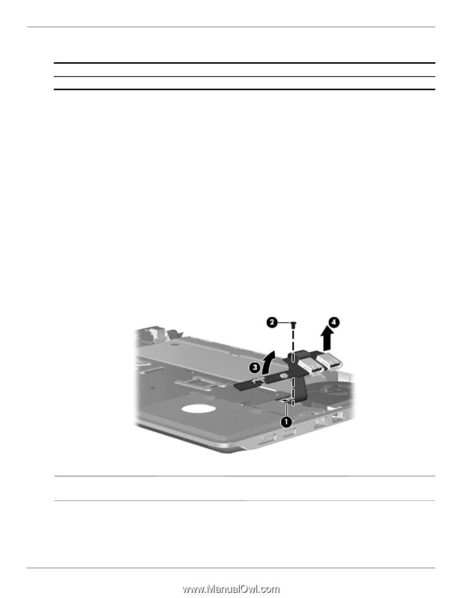
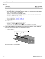
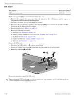
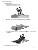
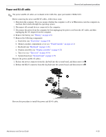
Removal and replacement procedures USB board Description USB board (includes cable) Spare part number 580700-001 Before removing the USB/power switch board, follow these steps: 1. Shut down the computer. If you are unsure whether the computer is off or in Hibernation, turn the computer on, and then shut it down through the operating system. 2. Disconnect all external devices connected to the computer. 3. Disconnect the power from the computer by first unplugging the power cord from the AC outlet, and then unplugging the AC adapter from the computer. 4. Remove the battery (see "Battery" on page 4-6). 5. Remove the following components: a. Hard drive (see "Hard drive" on page 4-9) b. Memory module compartment access cover (see "WLAN module" on page 4-12) c. Keyboard (see "Keyboard" on page 4-16) d. Display assembly (see "Display assembly" on page 4-22) e. Top cover (see "Top cover" on page 4-19) Remove the USB board: 1. Disconnect the USB board cable 1 from the system board. 2. Remove the Phillips 2.5×4.0 screw 2 to disengage the USB board from the system board. 3. Remove the USB board 3 and cable. Reverse this procedure to install the USB board. ✎ When replacing the USB board, make sure that the wireless and power actuators on the board, line up with the wireless and power switches on the base enclosure. 4-30 Maintenance and Service Guide
-
 1
1 -
2
-
3
-
4
-
5
-
6
-
7
-
8
-
9
-
10
-
11
-
12
-
13
-
14
-
15
-
16
-
17
-
18
-
19
-
20
-
21
-
22
-
23
-
24
-
25
-
26
-
27
-
28
-
29
-
30
-
31
-
32
-
33
-
34
-
35
-
36
-
37
-
38
-
39
-
40
-
41
-
42
-
43
-
44
-
45
-
46
-
47
-
48
-
49
-
50
-
51
-
52
-
53
-
54
-
55
-
56
-
57
-
58
-
59
-
60
-
 61
61 -
 62
62 -
 63
63 -
 64
64 -
 65
65 -
 66
66 -
 67
67 -
 68
68 -
 69
69 -
 70
70 -
 71
71 -
72
-
73
-
74
-
75
-
76
-
77
-
78
-
79
-
80
-
81
-
82
-
83
-
84
-
85
-
86
-
87
-
88
-
89
-
90
-
91
-
92
-
93
-
94
-
95
-
96
-
97
-
98
-
99
-
100
-
101
-
102
-
103
-
104
-
105
-
106
-
107
-
108
-
109
-
110
-
111
-
112
-
113
-
114
-
115
-
116
-
117
-
118
-
119
-
120
-
121
-
122
 |
 |