HP Presario V3600 Compaq Presario V3500 Notebook PC - Maintenance and Service - Page 73
CAUTION, Remove the five black Phillips PM2.5×7.0 screws
 |
View all HP Presario V3600 manuals
Add to My Manuals
Save this manual to your list of manuals |
Page 73 highlights
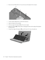
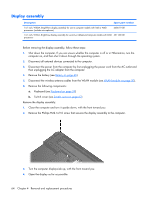
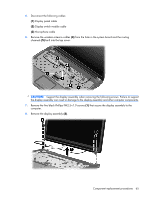
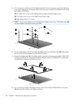
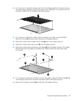
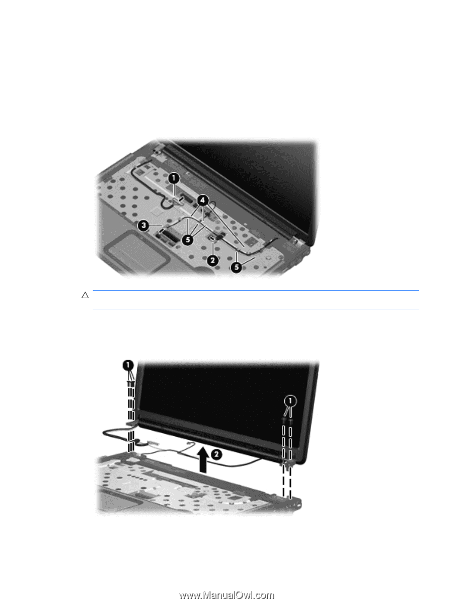
5. Disconnect the following cables: (1) Display panel cable (2) Display switch module cable (3) Microphone cable 6. Remove the wireless antenna cables (4) from the hole in the system board and the routing channels (5) built into the top cover. CAUTION: Support the display assembly when removing the following screws. Failure to support the display assembly can result in damage to the display assembly and other computer components. 7. Remove the five black Phillips PM2.5×7.0 screws (1) that secure the display assembly to the computer. 8. Remove the display assembly (2). Component replacement procedures 65
-
 1
1 -
2
-
3
-
4
-
5
-
6
-
7
-
8
-
9
-
10
-
11
-
12
-
13
-
14
-
15
-
16
-
17
-
18
-
19
-
20
-
21
-
22
-
23
-
24
-
25
-
26
-
27
-
28
-
29
-
30
-
31
-
32
-
33
-
34
-
35
-
36
-
37
-
38
-
39
-
40
-
41
-
42
-
43
-
44
-
45
-
46
-
47
-
48
-
49
-
50
-
51
-
52
-
53
-
54
-
55
-
56
-
57
-
58
-
59
-
60
-
61
-
62
-
63
-
64
-
65
-
66
-
67
-
 68
68 -
 69
69 -
 70
70 -
 71
71 -
 72
72 -
 73
73 -
 74
74 -
 75
75 -
 76
76 -
 77
77 -
 78
78 -
79
-
80
-
81
-
82
-
83
-
84
-
85
-
86
-
87
-
88
-
89
-
90
-
91
-
92
-
93
-
94
-
95
-
96
-
97
-
98
-
99
-
100
-
101
-
102
-
103
-
104
-
105
-
106
-
107
-
108
-
109
-
110
-
111
-
112
-
113
-
114
-
115
-
116
-
117
-
118
-
119
-
120
-
121
-
122
-
123
-
124
-
125
-
126
-
127
-
128
-
129
-
130
-
131
-
132
-
133
-
134
-
135
-
136
-
137
-
138
-
139
-
140
-
141
-
142
-
143
-
144
-
145
-
146
-
147
-
148
-
149
-
150
-
151
-
152
-
153
-
154
-
155
-
156
-
157
-
158
-
159
-
160
-
161
-
162
 |
 |
5
.
Disconnect the following cables:
(1)
Display panel cable
(2)
Display switch module cable
(3)
Microphone cable
6
.
Remove the wireless antenna cables
(4)
from the hole in the system board and the routing
channels
(5)
built into the top cover.
CAUTION:
Support the display assembly when removing the following screws. Failure to support
the display assembly can result in damage to the display assembly and other computer components.
7
.
Remove the five black Phillips PM2.5×7.0 screws
(1)
that secure the display assembly to the
computer.
8
.
Remove the display assembly
(2)
.
Component replacement procedures
65