HP Presario V3600 Compaq Presario V3500 Notebook PC - Maintenance and Service - Page 94
Remove the system board, by sliding it to the right at an angle until the connectors on the left side
 |
View all HP Presario V3600 manuals
Add to My Manuals
Save this manual to your list of manuals |
Page 94 highlights
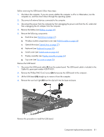
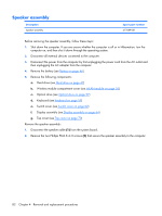
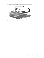
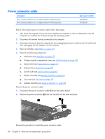
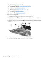
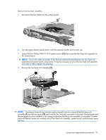
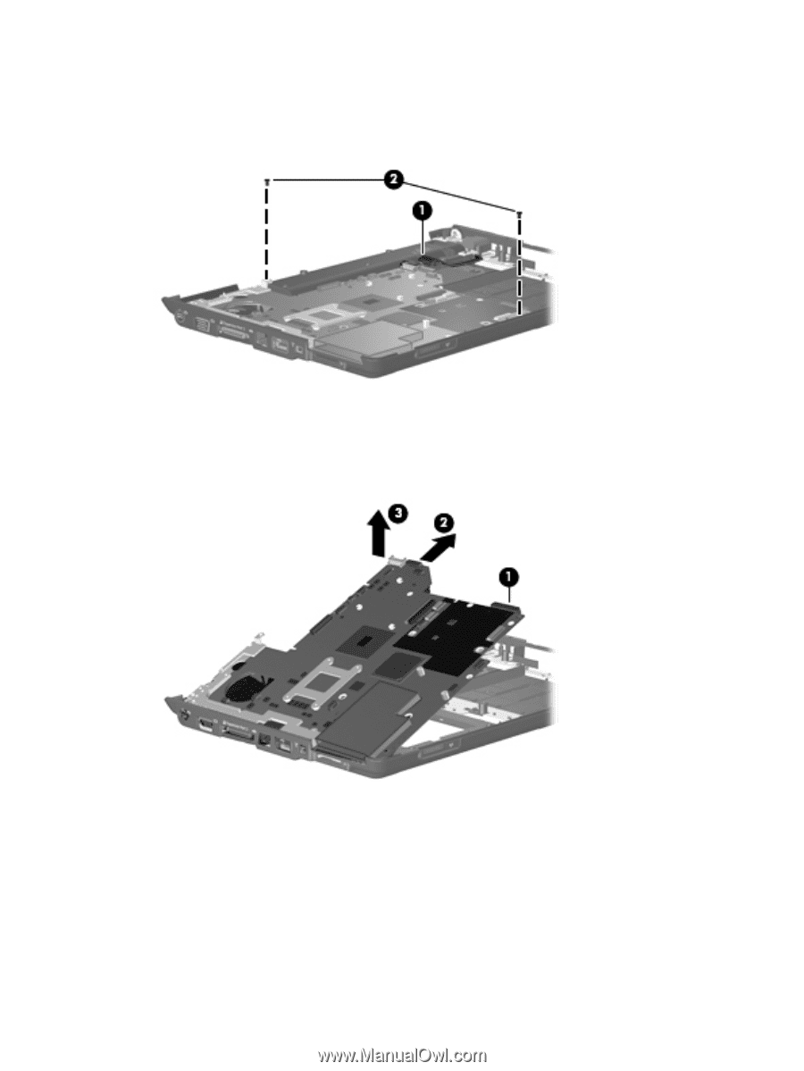
Remove the system board: 1. Disconnect the power connector cable (1) from the system board. 2. Remove the two black Phillips PM2.5×4.0 screws (2) that secure the system board to the computer. 3. Use the optical drive connector (1) to lift the right side of the system board until it rests at an angle. 4. Release the system board (2) by sliding it to the right at an angle until the connectors on the left side of the system board disengage from the base enclosure. 5. Remove the system board (3). 6. If it is necessary to replace the modem module cable, remove the RJ-11 connector (1) from the clip built into the base enclosure. 86 Chapter 4 Removal and replacement procedures
-
 1
1 -
2
-
3
-
4
-
5
-
6
-
7
-
8
-
9
-
10
-
11
-
12
-
13
-
14
-
15
-
16
-
17
-
18
-
19
-
20
-
21
-
22
-
23
-
24
-
25
-
26
-
27
-
28
-
29
-
30
-
31
-
32
-
33
-
34
-
35
-
36
-
37
-
38
-
39
-
40
-
41
-
42
-
43
-
44
-
45
-
46
-
47
-
48
-
49
-
50
-
51
-
52
-
53
-
54
-
55
-
56
-
57
-
58
-
59
-
60
-
61
-
62
-
63
-
64
-
65
-
66
-
67
-
68
-
69
-
70
-
71
-
72
-
73
-
74
-
75
-
76
-
77
-
78
-
79
-
80
-
81
-
82
-
83
-
84
-
85
-
86
-
87
-
88
-
 89
89 -
 90
90 -
 91
91 -
 92
92 -
 93
93 -
 94
94 -
 95
95 -
 96
96 -
 97
97 -
 98
98 -
 99
99 -
100
-
101
-
102
-
103
-
104
-
105
-
106
-
107
-
108
-
109
-
110
-
111
-
112
-
113
-
114
-
115
-
116
-
117
-
118
-
119
-
120
-
121
-
122
-
123
-
124
-
125
-
126
-
127
-
128
-
129
-
130
-
131
-
132
-
133
-
134
-
135
-
136
-
137
-
138
-
139
-
140
-
141
-
142
-
143
-
144
-
145
-
146
-
147
-
148
-
149
-
150
-
151
-
152
-
153
-
154
-
155
-
156
-
157
-
158
-
159
-
160
-
161
-
162
 |
 |
Remove the system board:
1
.
Disconnect the power connector cable
(1)
from the system board.
2
.
Remove the two black Phillips PM2.5×4.0 screws
(2)
that secure the system board to the computer.
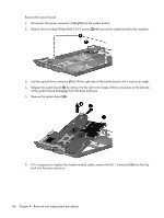
3
.
Use the optical drive connector
(1)
to lift the right side of the system board until it rests at an angle.
4
.
Release the system board
(2)
by sliding it to the right at an angle until the connectors on the left side
of the system board disengage from the base enclosure.
5
.
Remove the system board
(3)
.
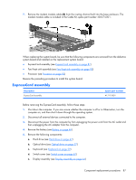
6
.
If it is necessary to replace the modem module cable, remove the RJ-11 connector
(1)
from the clip
built into the base enclosure.
86
Chapter
4
Removal and replacement procedures