HP Presario V3600 Compaq Presario V3500 Notebook PC - Maintenance and Service - Page 96
Turn the system board upside down, with the RJ-45 connector toward you.
 |
View all HP Presario V3600 manuals
Add to My Manuals
Save this manual to your list of manuals |
Page 96 highlights
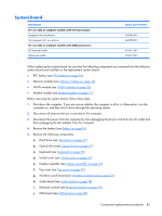
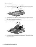
f. Top cover (see Top cover on page 70) g. Wireless switch board (see Wireless switch board on page 75) h. Audio board (see Audio board on page 78) i. Bluetooth module (see Bluetooth module on page 79) j. USB board (see USB board on page 80) k. System board (see System board on page 85) Remove the ExpressCard assembly: 1. Turn the system board upside down, with the RJ-45 connector toward you. 2. Lift the insulation material (1) from the system board to expose the ExpressCard assembly rear screws. 3. Remove the four Phillips PM2.0×4.0 screws (2) that secure the ExpressCard assembly to the system board. 4. Turn the system board right-side up, with the RJ-45 connector toward you. 88 Chapter 4 Removal and replacement procedures
-
 1
1 -
2
-
3
-
4
-
5
-
6
-
7
-
8
-
9
-
10
-
11
-
12
-
13
-
14
-
15
-
16
-
17
-
18
-
19
-
20
-
21
-
22
-
23
-
24
-
25
-
26
-
27
-
28
-
29
-
30
-
31
-
32
-
33
-
34
-
35
-
36
-
37
-
38
-
39
-
40
-
41
-
42
-
43
-
44
-
45
-
46
-
47
-
48
-
49
-
50
-
51
-
52
-
53
-
54
-
55
-
56
-
57
-
58
-
59
-
60
-
61
-
62
-
63
-
64
-
65
-
66
-
67
-
68
-
69
-
70
-
71
-
72
-
73
-
74
-
75
-
76
-
77
-
78
-
79
-
80
-
81
-
82
-
83
-
84
-
85
-
86
-
87
-
88
-
89
-
90
-
 91
91 -
 92
92 -
 93
93 -
 94
94 -
 95
95 -
 96
96 -
 97
97 -
 98
98 -
 99
99 -
 100
100 -
 101
101 -
102
-
103
-
104
-
105
-
106
-
107
-
108
-
109
-
110
-
111
-
112
-
113
-
114
-
115
-
116
-
117
-
118
-
119
-
120
-
121
-
122
-
123
-
124
-
125
-
126
-
127
-
128
-
129
-
130
-
131
-
132
-
133
-
134
-
135
-
136
-
137
-
138
-
139
-
140
-
141
-
142
-
143
-
144
-
145
-
146
-
147
-
148
-
149
-
150
-
151
-
152
-
153
-
154
-
155
-
156
-
157
-
158
-
159
-
160
-
161
-
162
 |
 |

f
.
Top cover (see
Top cover
on page
70
)
g
.
Wireless switch board (see
Wireless switch board
on page
75
)
h
.
Audio board (see
Audio board
on page
78
)
i
.
Bluetooth module (see
Bluetooth module
on page
79
)
j
.
USB board (see
USB board
on page
80
)
k
.
System board (see
System board
on page
85
)
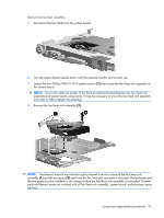
Remove the ExpressCard assembly:
1
.
Turn the system board upside down, with the RJ-45 connector toward you.
2
.
Lift the insulation material
(1)
from the system board to expose the ExpressCard assembly rear
screws.
3
.
Remove the four Phillips PM2.0×4.0 screws
(2)
that secure the ExpressCard assembly to the system
board.
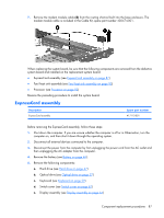
4
.
Turn the system board right-side up, with the RJ-45 connector toward you.
88
Chapter
4
Removal and replacement procedures