HP Presario V3600 Compaq Presario V3500 Notebook PC - Maintenance and Service - Page 89
Remove the Phillips PM2.5×4.0 screw, Before removing the USB board, follow these steps
 |
View all HP Presario V3600 manuals
Add to My Manuals
Save this manual to your list of manuals |
Page 89 highlights
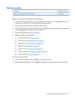
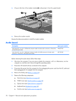
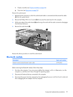
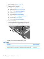
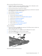
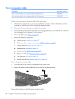
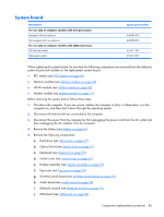
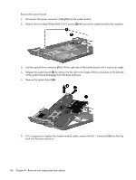
Before removing the USB board, follow these steps: 1. Shut down the computer. If you are unsure whether the computer is off or in Hibernation, turn the computer on, and then shut it down through the operating system. 2. Disconnect all external devices connected to the computer. 3. Disconnect the power from the computer by first unplugging the power cord from the AC outlet and then unplugging the AC adapter from the computer. 4. Remove the battery (see Battery on page 46). 5. Remove the following components: a. Hard drive (see Hard drive on page 47) b. Wireless module compartment cover (see WLAN module on page 50) c. Optical drive (see Optical drive on page 57) d. Keyboard (see Keyboard on page 59) e. Switch cover (see Switch cover on page 62) f. Display assembly (see Display assembly on page 64) g. Top cover (see Top cover on page 70) Remove the USB board: 1. Disconnect the USB board cable (1) from the system board. The USB board cable is included in the Cable Kit, spare part number 430474-001. 2. Remove the Phillips PM2.5×4.0 screw (2) that secures the USB board to the computer. 3. Lift the USB board (3) straight up to remove it from the computer. 4. Remove the num lock light (4) from the clip built into the base enclosure. Reverse this procedure to install the USB board. Component replacement procedures 81
-
 1
1 -
2
-
3
-
4
-
5
-
6
-
7
-
8
-
9
-
10
-
11
-
12
-
13
-
14
-
15
-
16
-
17
-
18
-
19
-
20
-
21
-
22
-
23
-
24
-
25
-
26
-
27
-
28
-
29
-
30
-
31
-
32
-
33
-
34
-
35
-
36
-
37
-
38
-
39
-
40
-
41
-
42
-
43
-
44
-
45
-
46
-
47
-
48
-
49
-
50
-
51
-
52
-
53
-
54
-
55
-
56
-
57
-
58
-
59
-
60
-
61
-
62
-
63
-
64
-
65
-
66
-
67
-
68
-
69
-
70
-
71
-
72
-
73
-
74
-
75
-
76
-
77
-
78
-
79
-
80
-
81
-
82
-
83
-
 84
84 -
 85
85 -
 86
86 -
 87
87 -
 88
88 -
 89
89 -
 90
90 -
 91
91 -
 92
92 -
 93
93 -
 94
94 -
95
-
96
-
97
-
98
-
99
-
100
-
101
-
102
-
103
-
104
-
105
-
106
-
107
-
108
-
109
-
110
-
111
-
112
-
113
-
114
-
115
-
116
-
117
-
118
-
119
-
120
-
121
-
122
-
123
-
124
-
125
-
126
-
127
-
128
-
129
-
130
-
131
-
132
-
133
-
134
-
135
-
136
-
137
-
138
-
139
-
140
-
141
-
142
-
143
-
144
-
145
-
146
-
147
-
148
-
149
-
150
-
151
-
152
-
153
-
154
-
155
-
156
-
157
-
158
-
159
-
160
-
161
-
162
 |
 |
