HP Presario V3600 Compaq Presario V3500 Notebook PC - Maintenance and Service - Page 95
ExpressCard assembly
 |
View all HP Presario V3600 manuals
Add to My Manuals
Save this manual to your list of manuals |
Page 95 highlights
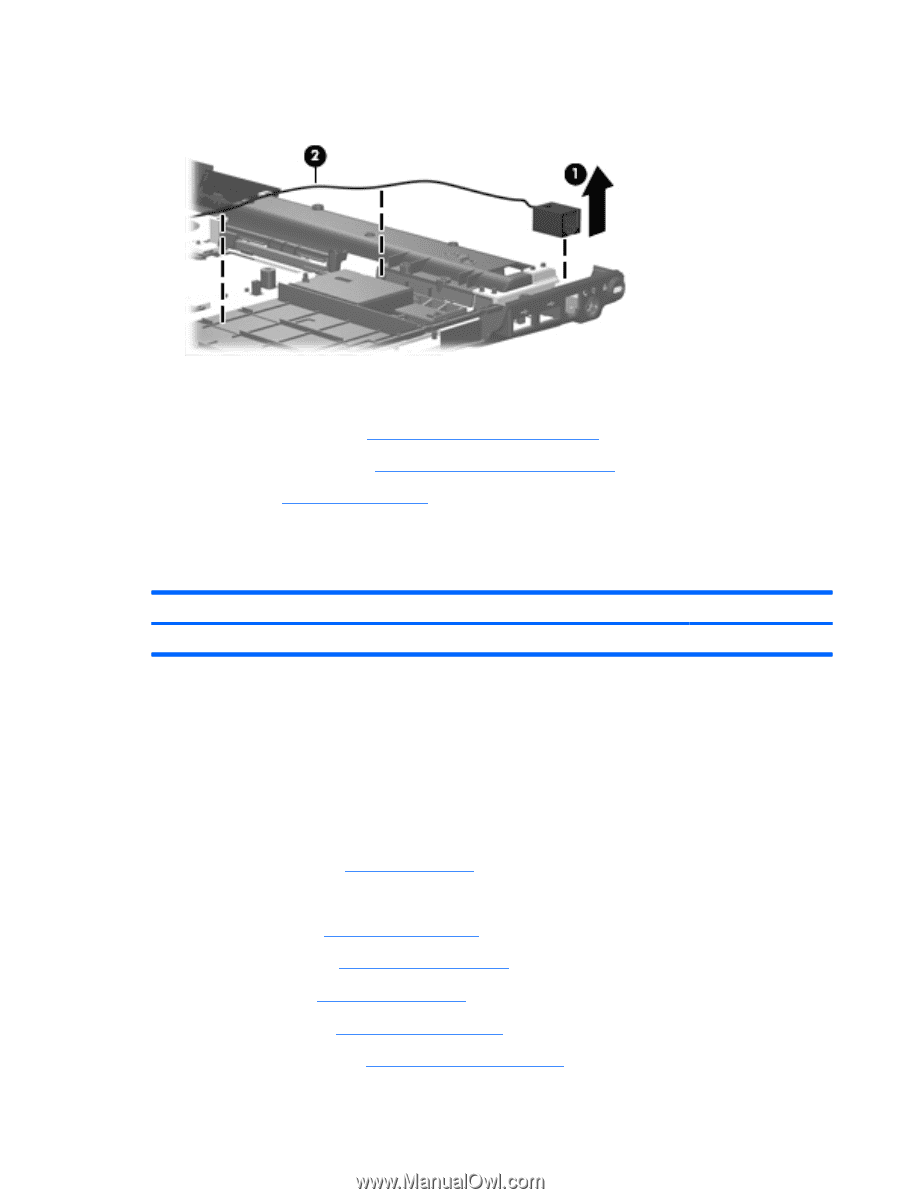
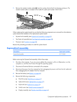
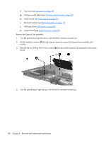
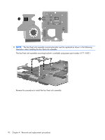
7. Remove the modem module cable (2) from the routing channel built into the base enclosure. The modem module cable is included in the Cable Kit, spare part number 430474-001. When replacing the system board, be sure that the following components are removed from the defective system board and installed on the replacement system board: ● ExpressCard assembly (see ExpressCard assembly on page 87) ● Fan/heat sink assembly (see Fan/heat sink assembly on page 90) ● Processor (see Processor on page 93) Reverse the preceding procedure to install the system board. ExpressCard assembly Description ExpressCard assembly Spare part number 417112-001 Before removing the ExpressCard assembly, follow these steps: 1. Shut down the computer. If you are unsure whether the computer is off or in Hibernation, turn the computer on, and then shut it down through the operating system. 2. Disconnect all external devices connected to the computer. 3. Disconnect the power from the computer by first unplugging the power cord from the AC outlet and then unplugging the AC adapter from the computer. 4. Remove the battery (see Battery on page 46). 5. Remove the following components: a. Hard drive (see Hard drive on page 47) b. Optical drive (see Optical drive on page 57) c. Keyboard (see Keyboard on page 59) d. Switch cover (see Switch cover on page 62) e. Display assembly (see Display assembly on page 64) Component replacement procedures 87
-
 1
1 -
2
-
3
-
4
-
5
-
6
-
7
-
8
-
9
-
10
-
11
-
12
-
13
-
14
-
15
-
16
-
17
-
18
-
19
-
20
-
21
-
22
-
23
-
24
-
25
-
26
-
27
-
28
-
29
-
30
-
31
-
32
-
33
-
34
-
35
-
36
-
37
-
38
-
39
-
40
-
41
-
42
-
43
-
44
-
45
-
46
-
47
-
48
-
49
-
50
-
51
-
52
-
53
-
54
-
55
-
56
-
57
-
58
-
59
-
60
-
61
-
62
-
63
-
64
-
65
-
66
-
67
-
68
-
69
-
70
-
71
-
72
-
73
-
74
-
75
-
76
-
77
-
78
-
79
-
80
-
81
-
82
-
83
-
84
-
85
-
86
-
87
-
88
-
89
-
 90
90 -
 91
91 -
 92
92 -
 93
93 -
 94
94 -
 95
95 -
 96
96 -
 97
97 -
 98
98 -
 99
99 -
 100
100 -
101
-
102
-
103
-
104
-
105
-
106
-
107
-
108
-
109
-
110
-
111
-
112
-
113
-
114
-
115
-
116
-
117
-
118
-
119
-
120
-
121
-
122
-
123
-
124
-
125
-
126
-
127
-
128
-
129
-
130
-
131
-
132
-
133
-
134
-
135
-
136
-
137
-
138
-
139
-
140
-
141
-
142
-
143
-
144
-
145
-
146
-
147
-
148
-
149
-
150
-
151
-
152
-
153
-
154
-
155
-
156
-
157
-
158
-
159
-
160
-
161
-
162
 |
 |