HP Pro 3520 PC Maintenance & Service Guide HP Pro 3520 All-in-One Business - Page 81
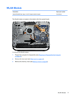
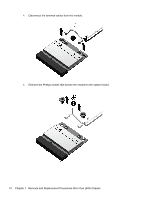
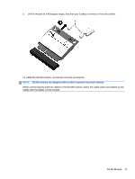
WLAN Module, When connecting the antenna cables to the WLAN module
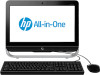 |
View all HP Pro 3520 PC manuals
Add to My Manuals
Save this manual to your list of manuals |
Page 81 highlights
6. Lift the module to a 45-degree angle, and then pull it away to remove it from the socket. To install the WLAN module, reverse the removal procedures. NOTE: WLAN modules are designed with a notch to prevent incorrect insertion. When connecting the antenna cables to the WLAN module, match the cable colors and labels on the cables with the labels on the module. WLAN Module 73
-
 1
1 -
2
-
3
-
4
-
5
-
6
-
7
-
8
-
9
-
10
-
11
-
12
-
13
-
14
-
15
-
16
-
17
-
18
-
19
-
20
-
21
-
22
-
23
-
24
-
25
-
26
-
27
-
28
-
29
-
30
-
31
-
32
-
33
-
34
-
35
-
36
-
37
-
38
-
39
-
40
-
41
-
42
-
43
-
44
-
45
-
46
-
47
-
48
-
49
-
50
-
51
-
52
-
53
-
54
-
55
-
56
-
57
-
58
-
59
-
60
-
61
-
62
-
63
-
64
-
65
-
66
-
67
-
68
-
69
-
70
-
71
-
72
-
73
-
74
-
75
-
 76
76 -
 77
77 -
 78
78 -
 79
79 -
 80
80 -
 81
81 -
 82
82 -
 83
83 -
 84
84 -
 85
85 -
 86
86 -
87
-
88
-
89
-
90
-
91
-
92
-
93
-
94
-
95
-
96
-
97
-
98
-
99
-
100
-
101
-
102
-
103
-
104
-
105
-
106
-
107
-
108
-
109
-
110
-
111
-
112
-
113
-
114
-
115
-
116
-
117
-
118
-
119
-
120
-
121
-
122
-
123
-
124
-
125
-
126
-
127
-
128
-
129
-
130
-
131
-
132
-
133
-
134
-
135
-
136
-
137
-
138
-
139
-
140
-
141
-
142
-
143
-
144
-
145
-
146
-
147
-
148
-
149
-
150
-
151
-
152
 |
 |

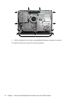
6.
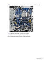
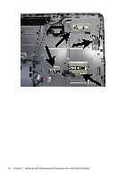
Lift the module to a 45-degree angle, and then pull it away to remove it from the socket.
To install the WLAN module, reverse the removal procedures.
NOTE:
WLAN modules are designed with a notch to prevent incorrect insertion.
When connecting the antenna cables to the WLAN module, match the cable colors and labels on the
cables with the labels on the module.
WLAN Module
73