HP Pro 3520 PC Maintenance & Service Guide HP Pro 3520 All-in-One Business - Page 82
System Board
 |
View all HP Pro 3520 PC manuals
Add to My Manuals
Save this manual to your list of manuals |
Page 82 highlights
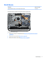
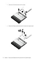
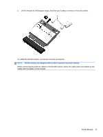
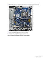
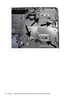
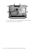
System Board Description System board for use in models with Windows 8 with no Digital Product Key (DPK) System board for use in models with Windows 8 Standard System board for use in models with Windows 8 Professional Thermal pads, PCH Thermal pads, Vagx Thermal pads, Voore Thermal pads, SODIMM Spare part number 703643-001 703643-501 703643-601 709842-001 709843-001 709844-001 709845-001 The system board is secured with nine screws. To remove the system board: 1. Prepare the computer for disassembly (see Preparing to Disassemble the Computer on page 40). 2. Remove the rear cover (see Rear Cover on page 41). 3. Remove the system board cover (see System Board Cover on page 61). 4. Remove the memory module (see Memory on page 46). 5. Remove the WLAN module (see WLAN Module on page 71). 6. Remove the heat sink (Heat sink/thermal module on page 65). 7. Remove the processor (Processor on page 67). 8. Remove the webcam module from the front bezel (Webcam Module on page 58). 9. Disconnect all cables from the system board, noting their location for reinstallation. 74 Chapter 7 Removal and Replacement Procedures All-in One (AIO) Chassis
-
 1
1 -
2
-
3
-
4
-
5
-
6
-
7
-
8
-
9
-
10
-
11
-
12
-
13
-
14
-
15
-
16
-
17
-
18
-
19
-
20
-
21
-
22
-
23
-
24
-
25
-
26
-
27
-
28
-
29
-
30
-
31
-
32
-
33
-
34
-
35
-
36
-
37
-
38
-
39
-
40
-
41
-
42
-
43
-
44
-
45
-
46
-
47
-
48
-
49
-
50
-
51
-
52
-
53
-
54
-
55
-
56
-
57
-
58
-
59
-
60
-
61
-
62
-
63
-
64
-
65
-
66
-
67
-
68
-
69
-
70
-
71
-
72
-
73
-
74
-
75
-
76
-
 77
77 -
 78
78 -
 79
79 -
 80
80 -
 81
81 -
 82
82 -
 83
83 -
 84
84 -
 85
85 -
 86
86 -
 87
87 -
88
-
89
-
90
-
91
-
92
-
93
-
94
-
95
-
96
-
97
-
98
-
99
-
100
-
101
-
102
-
103
-
104
-
105
-
106
-
107
-
108
-
109
-
110
-
111
-
112
-
113
-
114
-
115
-
116
-
117
-
118
-
119
-
120
-
121
-
122
-
123
-
124
-
125
-
126
-
127
-
128
-
129
-
130
-
131
-
132
-
133
-
134
-
135
-
136
-
137
-
138
-
139
-
140
-
141
-
142
-
143
-
144
-
145
-
146
-
147
-
148
-
149
-
150
-
151
-
152
 |
 |
