HP ProBook 4740s HP ProBook 4740s Notebook PC - Maintenance and Service Guide - Page 72
Remove the system board, Disconnect the power cable
 |
View all HP ProBook 4740s manuals
Add to My Manuals
Save this manual to your list of manuals |
Page 72 highlights
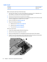
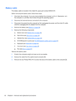
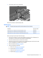
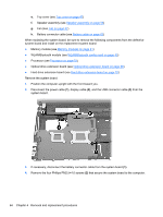
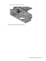
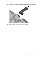
e. Top cover (see Top cover on page 47) f. Speaker assembly (see Speaker assembly on page 58) g. Fan (see Fan on page 57) h. Battery connector cable (see Battery cable on page 62) When replacing the system board, be sure to remove the following components from the defective system board and install on the replacement system board: ● Memory module (see Memory modules on page 41) ● WLAN/Bluetooth module (see WLAN/Bluetooth combo card on page 43) ● Processor (see Processor on page 73) ● Optical drive extension board (see Optical drive extension board on page 68) ● Hard drive extension board (see Hard drive extension board on page 70) Remove the system board: 1. Position the computer upright with the front toward you. 2. Disconnect the power cable (1), display cable (2), and the USB connector cable (3) from the system board. 3. If necessary, disconnect the battery connector cable from the system board (1). 4. Remove the four Phillips PM2.5×4.0 screws (2) that secure the system board to the computer. 64 Chapter 4 Removal and replacement procedures
-
 1
1 -
2
-
3
-
4
-
5
-
6
-
7
-
8
-
9
-
10
-
11
-
12
-
13
-
14
-
15
-
16
-
17
-
18
-
19
-
20
-
21
-
22
-
23
-
24
-
25
-
26
-
27
-
28
-
29
-
30
-
31
-
32
-
33
-
34
-
35
-
36
-
37
-
38
-
39
-
40
-
41
-
42
-
43
-
44
-
45
-
46
-
47
-
48
-
49
-
50
-
51
-
52
-
53
-
54
-
55
-
56
-
57
-
58
-
59
-
60
-
61
-
62
-
63
-
64
-
65
-
66
-
 67
67 -
 68
68 -
 69
69 -
 70
70 -
 71
71 -
 72
72 -
 73
73 -
 74
74 -
 75
75 -
 76
76 -
 77
77 -
78
-
79
-
80
-
81
-
82
-
83
-
84
-
85
-
86
-
87
-
88
-
89
-
90
-
91
-
92
-
93
-
94
-
95
-
96
-
97
-
98
-
99
-
100
-
101
-
102
-
103
-
104
-
105
-
106
-
107
-
108
-
109
-
110
-
111
-
112
-
113
-
114
-
115
-
116
-
117
-
118
-
119
-
120
-
121
-
122
-
123
-
124
-
125
 |
 |