HP ProBook 4740s HP ProBook 4740s Notebook PC - Maintenance and Service Guide - Page 87
Remove the four Torx T8M2.5×8.0 screws, on the top of
 |
View all HP ProBook 4740s manuals
Add to My Manuals
Save this manual to your list of manuals |
Page 87 highlights
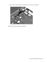
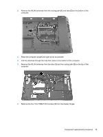
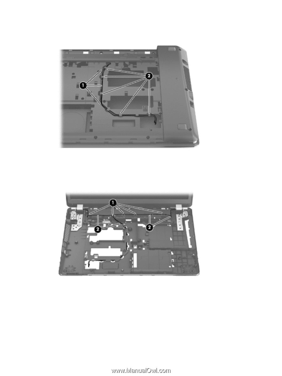
2. Remove the WLAN antennas from the routing path (1) and tabs (2) on the bottom of the computer. 3. Place the computer upright and open as far as possible. 4. Pull the antennas through the hole that routes to the bottom of the computer. 5. Remove the WLAN antennas from the tabs (1) and the routing path (2) on the top of the computer. 6. Remove the four Torx T8M2.5×8.0 screws (1) from the display hinges. Component replacement procedures 79
-
 1
1 -
2
-
3
-
4
-
5
-
6
-
7
-
8
-
9
-
10
-
11
-
12
-
13
-
14
-
15
-
16
-
17
-
18
-
19
-
20
-
21
-
22
-
23
-
24
-
25
-
26
-
27
-
28
-
29
-
30
-
31
-
32
-
33
-
34
-
35
-
36
-
37
-
38
-
39
-
40
-
41
-
42
-
43
-
44
-
45
-
46
-
47
-
48
-
49
-
50
-
51
-
52
-
53
-
54
-
55
-
56
-
57
-
58
-
59
-
60
-
61
-
62
-
63
-
64
-
65
-
66
-
67
-
68
-
69
-
70
-
71
-
72
-
73
-
74
-
75
-
76
-
77
-
78
-
79
-
80
-
81
-
 82
82 -
 83
83 -
 84
84 -
 85
85 -
 86
86 -
 87
87 -
 88
88 -
 89
89 -
 90
90 -
 91
91 -
 92
92 -
93
-
94
-
95
-
96
-
97
-
98
-
99
-
100
-
101
-
102
-
103
-
104
-
105
-
106
-
107
-
108
-
109
-
110
-
111
-
112
-
113
-
114
-
115
-
116
-
117
-
118
-
119
-
120
-
121
-
122
-
123
-
124
-
125
 |
 |
2.
Remove the WLAN antennas from the routing path
(1)
and tabs
(2)
on the bottom of the
computer.
3.
Place the computer upright and open as far as possible.
4.
Pull the antennas through the hole that routes to the bottom of the computer.
5.
Remove the WLAN antennas from the tabs
(1)
and the routing path
(2)
on the top of the
computer.
6.
Remove the four Torx T8M2.5×8.0 screws
(1)
from the display hinges.
Component replacement procedures
79