HP ProBook 4740s HP ProBook 4740s Notebook PC - Maintenance and Service Guide - Page 92
Position the display panel and hinge assembly upright., that secure each display hinge to the display
 |
View all HP ProBook 4740s manuals
Add to My Manuals
Save this manual to your list of manuals |
Page 92 highlights
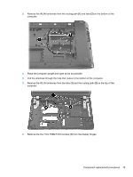
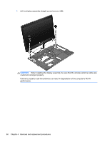
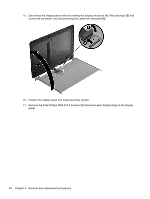
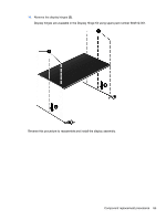
15. Disconnect the display panel cable by rotating the display enclosure (1), lifting the tape (2) that covers the connector, and disconnecting the cable from the panel (3). 16. Position the display panel and hinge assembly upright. 17. Remove the three Phillips PM2.0×3.0 screws (1) that secure each display hinge to the display panel. 84 Chapter 4 Removal and replacement procedures
-
 1
1 -
2
-
3
-
4
-
5
-
6
-
7
-
8
-
9
-
10
-
11
-
12
-
13
-
14
-
15
-
16
-
17
-
18
-
19
-
20
-
21
-
22
-
23
-
24
-
25
-
26
-
27
-
28
-
29
-
30
-
31
-
32
-
33
-
34
-
35
-
36
-
37
-
38
-
39
-
40
-
41
-
42
-
43
-
44
-
45
-
46
-
47
-
48
-
49
-
50
-
51
-
52
-
53
-
54
-
55
-
56
-
57
-
58
-
59
-
60
-
61
-
62
-
63
-
64
-
65
-
66
-
67
-
68
-
69
-
70
-
71
-
72
-
73
-
74
-
75
-
76
-
77
-
78
-
79
-
80
-
81
-
82
-
83
-
84
-
85
-
86
-
 87
87 -
 88
88 -
 89
89 -
 90
90 -
 91
91 -
 92
92 -
 93
93 -
 94
94 -
 95
95 -
 96
96 -
 97
97 -
98
-
99
-
100
-
101
-
102
-
103
-
104
-
105
-
106
-
107
-
108
-
109
-
110
-
111
-
112
-
113
-
114
-
115
-
116
-
117
-
118
-
119
-
120
-
121
-
122
-
123
-
124
-
125
 |
 |
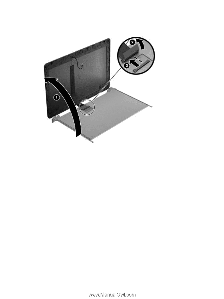
15.
Disconnect the display panel cable by rotating the display enclosure
(1)
, lifting the tape
(2)
that
covers the connector, and disconnecting the cable from the panel
(3)
.
16.
Position the display panel and hinge assembly upright.
17.
Remove the three Phillips PM2.0×3.0 screws
(1)
that secure each display hinge to the display
panel.
84
Chapter 4
Removal and replacement procedures