HP ProBook 4740s HP ProBook 4740s Notebook PC - Maintenance and Service Guide - Page 84
Latch assembly, The latch mechanism includes a small spring. Note the location of the spring.
 |
View all HP ProBook 4740s manuals
Add to My Manuals
Save this manual to your list of manuals |
Page 84 highlights
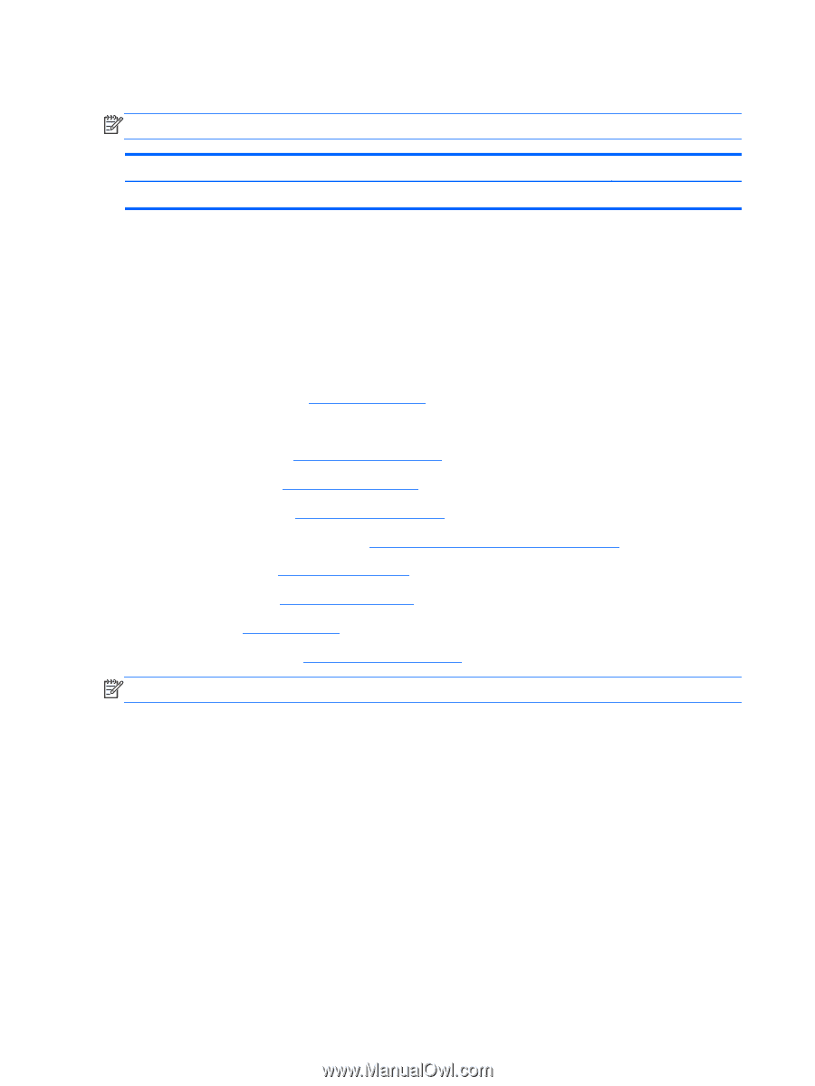
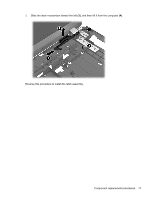
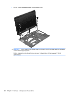
Latch assembly NOTE: The Latch Kit includes the left and right latches, knob, screws, and spring. Description Latch Kit Spare part number 684635-001 Before removing the latch assembly, follow these steps: 1. Shut down the computer. If you are unsure whether the computer is off or in Hibernation, turn the computer on, and then shut it down through the operating system. 2. Disconnect all external devices connected to the computer. 3. Disconnect the power from the computer by first unplugging the power cord from the AC outlet, and then unplugging the AC adapter from the computer. 4. Remove the battery (see Battery on page 33). 5. Remove the following components: a. Bottom door (see Bottom door on page 34). b. Hard drive (see Hard drive on page 38) c. Optical drive (see Optical drive on page 36) d. WLAN/Bluetooth module (see WLAN/Bluetooth combo card on page 43) e. Keyboard (see Keyboard on page 45) f. Top cover (see Top cover on page 47) g. Fan (see Fan on page 57) h. System board (see System board on page 63) NOTE: The latch mechanism includes a small spring. Note the location of the spring. Remove the latch assembly: 1. Position the computer upright and open as far as possible. 2. Remove the spring (1) from the tab on the base enclosure (2). 76 Chapter 4 Removal and replacement procedures
-
 1
1 -
2
-
3
-
4
-
5
-
6
-
7
-
8
-
9
-
10
-
11
-
12
-
13
-
14
-
15
-
16
-
17
-
18
-
19
-
20
-
21
-
22
-
23
-
24
-
25
-
26
-
27
-
28
-
29
-
30
-
31
-
32
-
33
-
34
-
35
-
36
-
37
-
38
-
39
-
40
-
41
-
42
-
43
-
44
-
45
-
46
-
47
-
48
-
49
-
50
-
51
-
52
-
53
-
54
-
55
-
56
-
57
-
58
-
59
-
60
-
61
-
62
-
63
-
64
-
65
-
66
-
67
-
68
-
69
-
70
-
71
-
72
-
73
-
74
-
75
-
76
-
77
-
78
-
 79
79 -
 80
80 -
 81
81 -
 82
82 -
 83
83 -
 84
84 -
 85
85 -
 86
86 -
 87
87 -
 88
88 -
 89
89 -
90
-
91
-
92
-
93
-
94
-
95
-
96
-
97
-
98
-
99
-
100
-
101
-
102
-
103
-
104
-
105
-
106
-
107
-
108
-
109
-
110
-
111
-
112
-
113
-
114
-
115
-
116
-
117
-
118
-
119
-
120
-
121
-
122
-
123
-
124
-
125
 |
 |