HP ProLiant SL165z HP ProLiant SL165z G6 Server Maintenance and Service Guide - Page 31
Cable Connections, Table 1, Cable, Cable Designator, System Board Designator
 |
View all HP ProLiant SL165z manuals
Add to My Manuals
Save this manual to your list of manuals |
Page 31 highlights
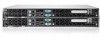
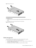
Cable Connections The following table provides information about switching power supply cable connector labels. Table 1 Cable connections Cable 8-pin power connector 24-pin power connector 8-pin power connector Switching Power Supply To Power supply Power supply Power supply System board Power Supply Management Interface connector Cable Designator P24 P21 P23 J1 (MB) The following table provides the system board designators that various cables plug into. For more detailed information about system board components, see system board components. Table 2 Cable connections Cable Internal USB connector 18-Pin front panel connector SATA1 connector SATA2 connector Front board cable 1 To USB Front panel SATA1 SATA2 Front i/o board System Board Designator J21 P10 SATA0 SATA1 J1 (front board) Removal and Replacement Procedures 31
-
 1
1 -
2
-
3
-
4
-
5
-
6
-
7
-
8
-
9
-
10
-
11
-
12
-
13
-
14
-
15
-
16
-
17
-
18
-
19
-
20
-
21
-
22
-
23
-
24
-
25
-
 26
26 -
 27
27 -
 28
28 -
 29
29 -
 30
30 -
 31
31 -
 32
32 -
 33
33 -
 34
34 -
 35
35 -
 36
36 -
37
-
38
-
39
-
40
-
41
-
42
-
43
-
44
-
45
-
46
-
47
-
48
-
49
-
50
-
51
-
52
-
53
-
54
-
55
-
56
-
57
-
58
-
59
-
60
-
61
-
62
-
63
-
64
-
65
-
66
-
67
-
68
-
69
-
70
-
71
-
72
-
73
-
74
-
75
-
76
-
77
-
78
-
79
-
80
 |
 |
